![Infoitech - [B]logging](https://blog.infoitech.co.uk/content/images/2021/04/youtube-small-cover-1.png)
Proxmox Cluster (Tucana Cloud) - Create a new VLAN - Part VI
Let's document the steps to create a new VLAN into the tucana cloud.
1) Interfaces & VLAN
We first will log into our primary pfSense firewall and will navigate to Interfaces > VLANs > Add :
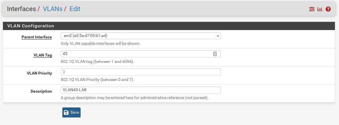
The tucana cloud uses tags ending in 5 for the third octect to avoid subnets overlapping with my home ones that end with 0 in the class C addresses 192.168.xxx.xxx.
We now need to assign the newly created VLAN to an interface as below :
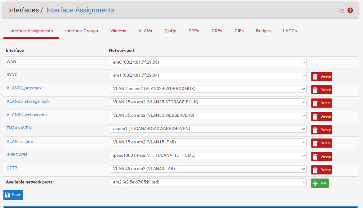
Available network ports and select the newly created VLAN.Let's define an IP Address and enable our interface.
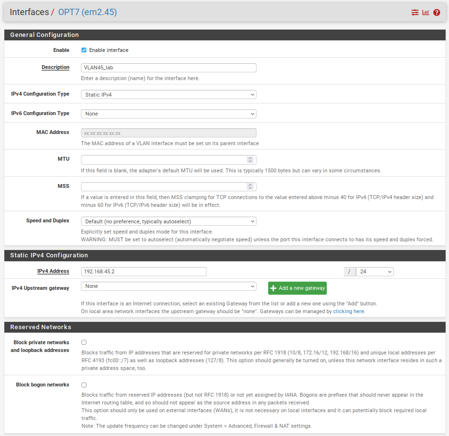
You might have noticed that the IP ends in .2 and we are using .2 because the tucana cloud has a High Availability Cluster of firewalls that requires 3 IP addresses from the range to operate. The Virtual IP and also gateway will use .1 and the secondary firewall .3.
Repeat the steps above in the secondary firewall.
Remember to change the IP Address to .3 on the secondary firewall.We can now apply all the changes to both firewalls if you did not already.
2) Virtual IP
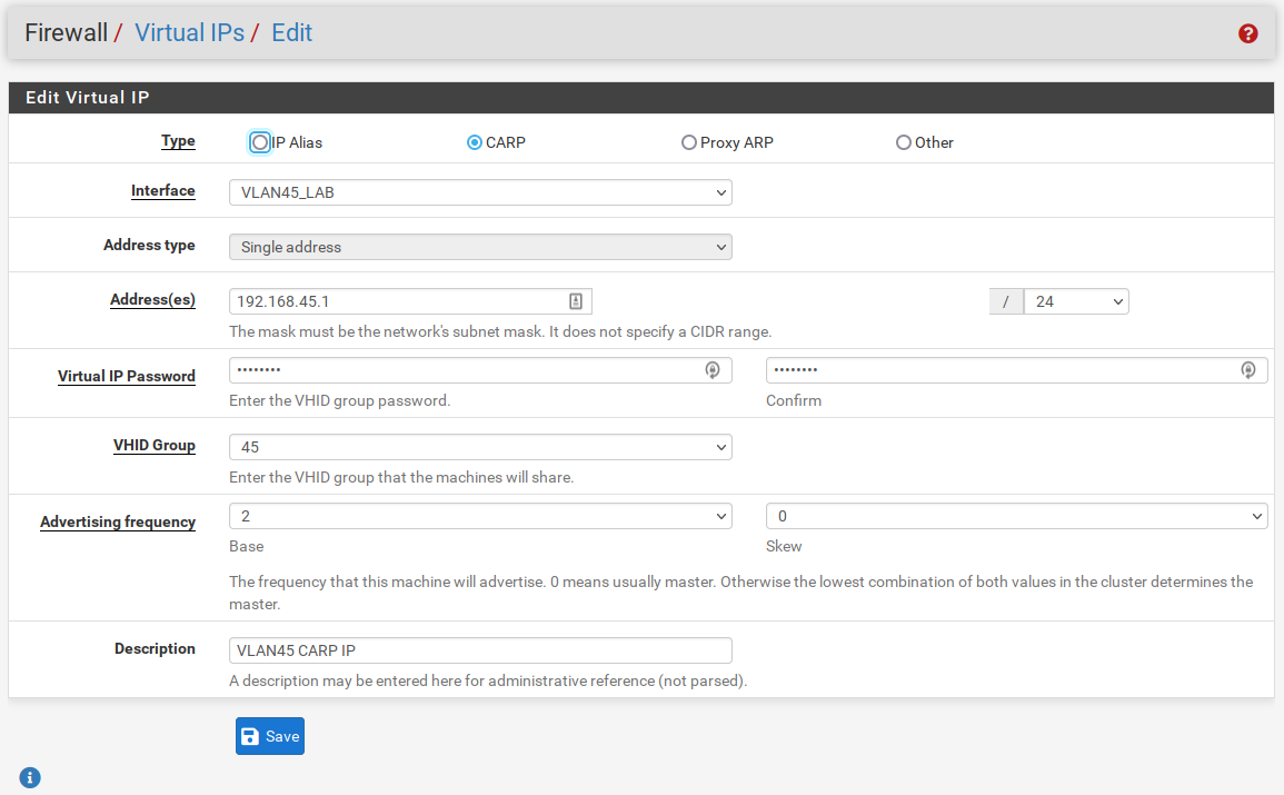
All the changes from now on will be done on the primary firewall, since we have a HA Cluster the changes will sync between the firewalls.
Create the CARP IP in the primary firewall as the picture below :
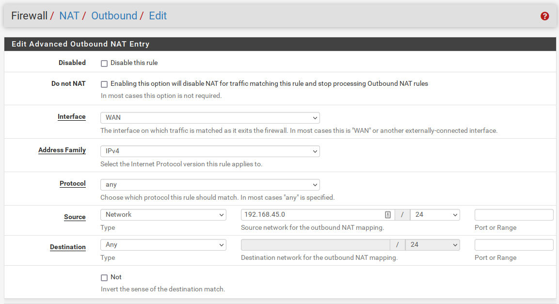
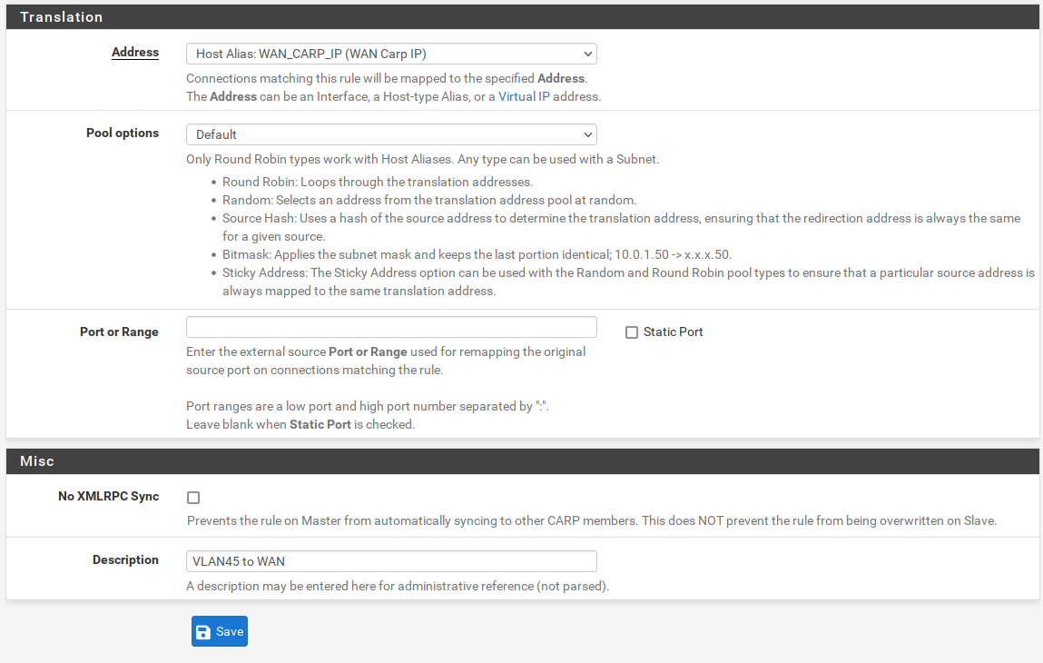
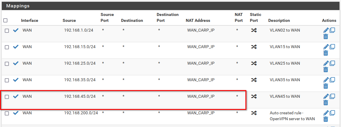
3) Outbound NAT
We need to NAT the outbound traffic to our WAN CARP IP.
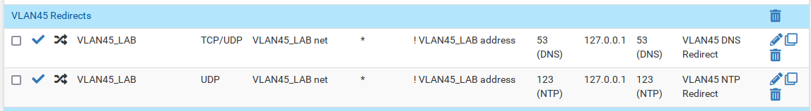
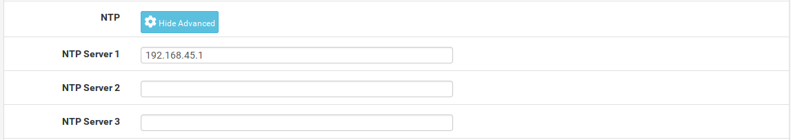
4) DNS and NTP forwarding
The tucana cloud firewalls capture all DNS and NTP traffic redirecting it to the firewall. This is implemented to avoid internal hosts querying external DNS or NTP servers.
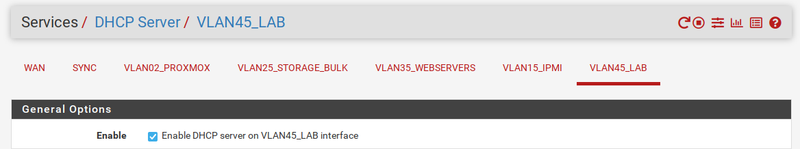
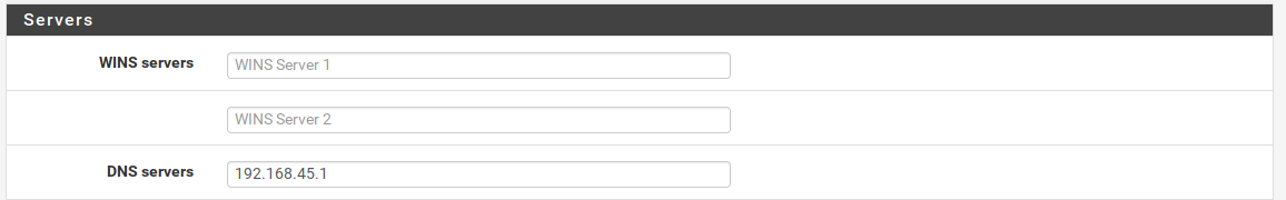
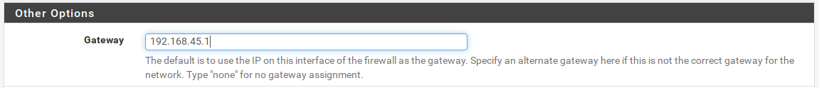
5) DHCP Server
Let's setup our the DHCP server on our subnet.


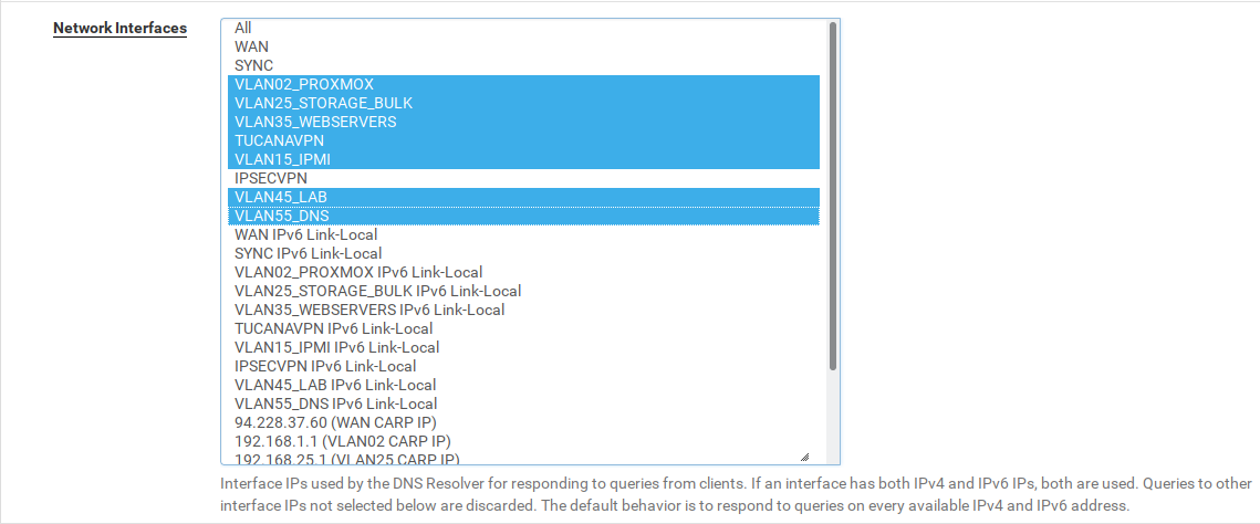
6) DNS
We need to allow the DNS resolver in our new subnet.
Navigate to Services > DNS Resolver and change the option Network Interfaces as the picture :
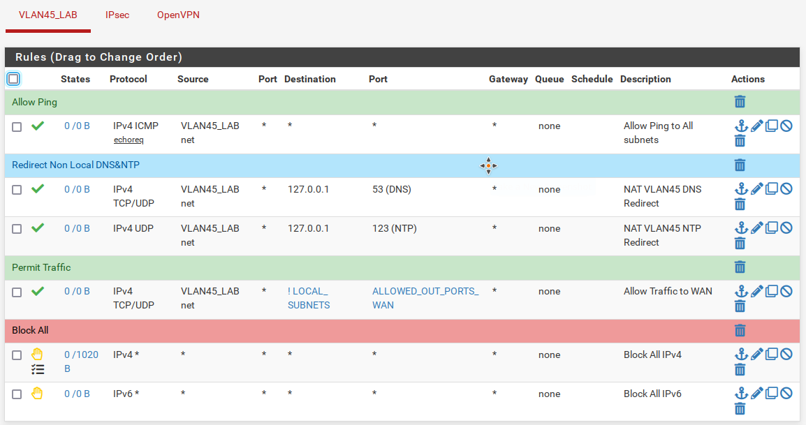
7) Firewall Rules
And finally we need to create firewall rules to the newly created subnet.
Navigate to Firewall > Rules and add rules to match the below:
Proxmox Changes
We now need to change our virtual networking enviroment in our proxmox servers to allow the traffic to flow between the firewalls and the hosts.
The changes consists of :
1) Add the VLAN to the FW1 & FW2 trunk interface.
- For persistent changes we also need to update the firewalls network configuration files to allow that the startup network scripts set up the network on reboot.
2) Add the VLAN to physical trunk.
- For persistent changes we also need to update the physical trunk network configuration files to allow that the startup network scripts set up the network on reboot.
3) Add the VMs interfaces to the bridge and adjust the VLAN tag.
- Create the VMs network configuration files to allow the network scripts to adjust the tags when the VMs are turned on/off. Proxmox destroys the VMs interfaces and recreates when the VM is turned on or off respectively.
We can visualise the above in the diagram below :
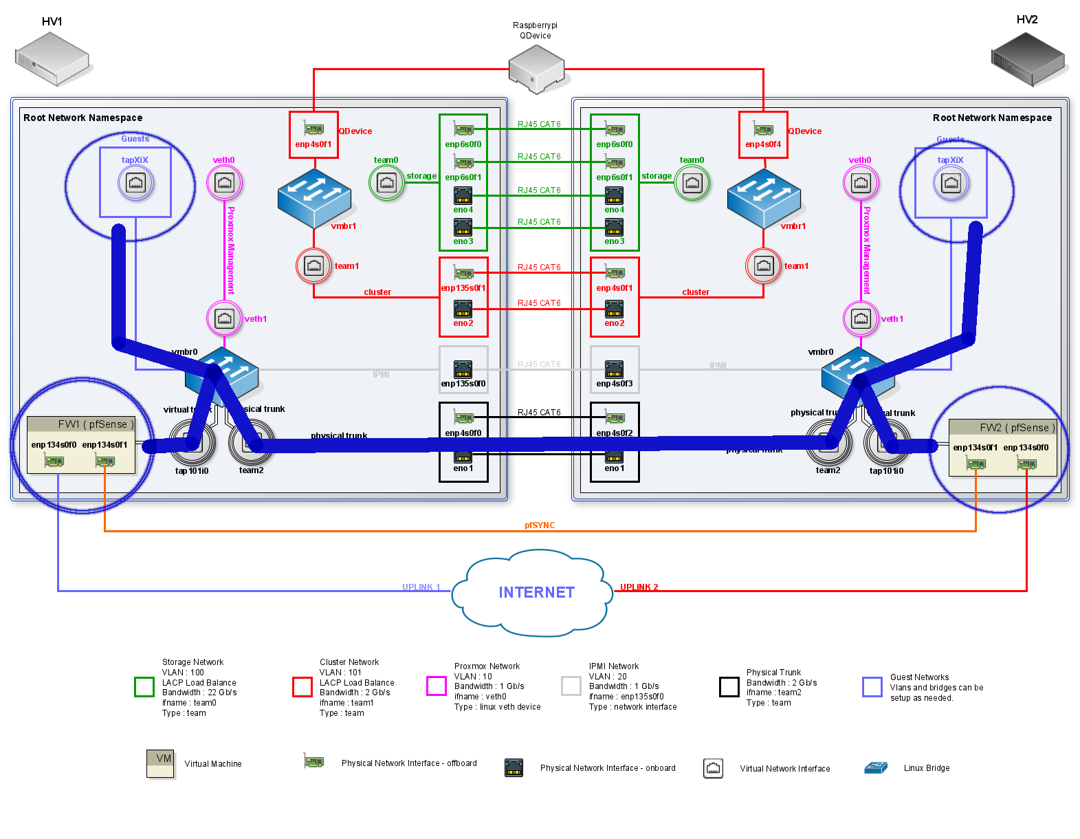
The changes listed above will allow traffic to flow between the Hypervisors. The hosts on the same VLAN will see each other even tough not being in the same Hypervisor.
Let's start changing the HV1 :
1) Add VLAN to FW1 Trunk
root@hv1:~# bridge vlan add vid 45 dev tap101i0 masterFor persistent changes we need to add the VLAN to the firewall network config file:
[
        {
          "interfaces":{
            "ifname":"tap101i0",
            "br":"vmbr0",
            "vlan":[
              {"vid":"2", "pvid":"0"},
              {"vid":"15", "pvid":"0"},
              {"vid":"25", "pvid":"0"},
              {"vid":"35", "pvid":"0"},
              {"vid":"45", "pvid":"0"}
            ]
          }
        }
]2) Add VLAN to the Physical Trunk
root@hv1:~/network/config# bridge vlan add vid 45 dev team2 masterLet's change the team2 config file for persistent changes:
{
        "team0": {
                "ip":"192.168.100.1/24",
                "vlan":0,
                "bridge":"0"
        },
        "team1":{
                "ip":"192.168.101.1/24",
                "vlan":0,
                "bridge":"0"
        },
        "team2": {
                "ip":"0",
                "vlan":[
                        { "vid":"2","pvid":"0" },
                        { "vid":"15","pvid":"0" },
                        { "vid":"25","pvid":"0" },
                        { "vid":"35","pvid":"0" },
                        { "vid":"45","pvid":"0" }
                ],
                "bridge":"vmbr0"
        }
}The steps above should now be repeated in the HV2.
And after the changes the bridge in both Hypervisors should have the following configuration for team2 and tap101i0:
root@hv1:~/network/config# bridge vlan show
port    vlan ids
enp135s0f0       15 PVID Egress Untagged

vmbr0   None
veth1    2 PVID Egress Untagged

team2    2
         15
         25
         35
         45

tap101i0         2
         15
         25
         35
         45

tap102i0         35 PVID Egress Untagged

tap100i0 25 PVID Egress UntaggedAt this point the VLAN has been deployed and we are able to ping across the firewalls.
Let's briefly test reachability between the firewalls and finalise our deployment setting our guests.
[2.5.2-RELEASE][admin@hv2-fw2.localdomain]/root: ifconfig em2.45
em2.45: flags=8943<UP,BROADCAST,RUNNING,PROMISC,SIMPLEX,MULTICAST> metric 0 mtu 1500
        ...
        inet 192.168.45.3 netmask 0xffffff00 broadcast 192.168.45.255
        inet 192.168.45.1 netmask 0xffffff00 broadcast 192.168.45.255 vhid 45
        groups: vlan
        carp: BACKUP vhid 45 advbase 2 advskew 100
        vlan: 45 vlanpcp: 0 parent interface: em2
        ...

[2.5.2-RELEASE][admin@hv2-fw2.localdomain]/root: ping 192.168.45.2
PING 192.168.45.2 (192.168.45.2): 56 data bytes
64 bytes from 192.168.45.2: icmp_seq=0 ttl=64 time=1.576 ms
64 bytes from 192.168.45.2: icmp_seq=1 ttl=64 time=1.013 ms
64 bytes from 192.168.45.2: icmp_seq=2 ttl=64 time=0.913 ms
^C
--- 192.168.45.2 ping statistics ---
3 packets transmitted, 3 packets received, 0.0% packet loss
round-trip min/avg/max/stddev = 0.913/1.167/1.576/0.292 ms3) Add VM to the Bridge
This step is still not completed in the host. I have found that the scripts to add the interfaces and VLANs to the bridge need to be rewritten to deal with VMs that has more then one interface. Therefore, I will leave this session to be documented when the scripts are changed.
However, we can use the commands below to manually add the VLANs.
bridge vlan del vid 1 dev tap103i0 masterbridge vlan add dev tap103i0 vid 75 pvid untagged masterWith all the steps described above we have added a new VLAN across our firewalls and two nodes. These steps can and will be automated in the future. I hope that this article helped you and see you in the next adventure.