![Infoitech - [B]logging](https://blog.infoitech.co.uk/content/images/2021/04/youtube-small-cover-1.png)
Cisco CCNP - SPCOR (350-501) Certification
Summary
A new revision to the Cisco CCNP is coming on 19 September 2024.
The exam topics for the SPCOR 350-501 can be found on this link.
The release notes list all the upcoming changes to the new CCNP SPCOR certification.
CCIE Service Provider is also changing. CCIE is the Cisco LAB exam and the release notes list the changes coming.
CCNP exams can be found here under Service Provider.
List of Cisco Images and its features.
Exam Considerations

The tips for the CCNP are as follows:
- Do not study the day before the exam.
- Create LABs, breaking and fixing them to learn.
- Additional reading: https://njrusmc.net/pub/pub.html
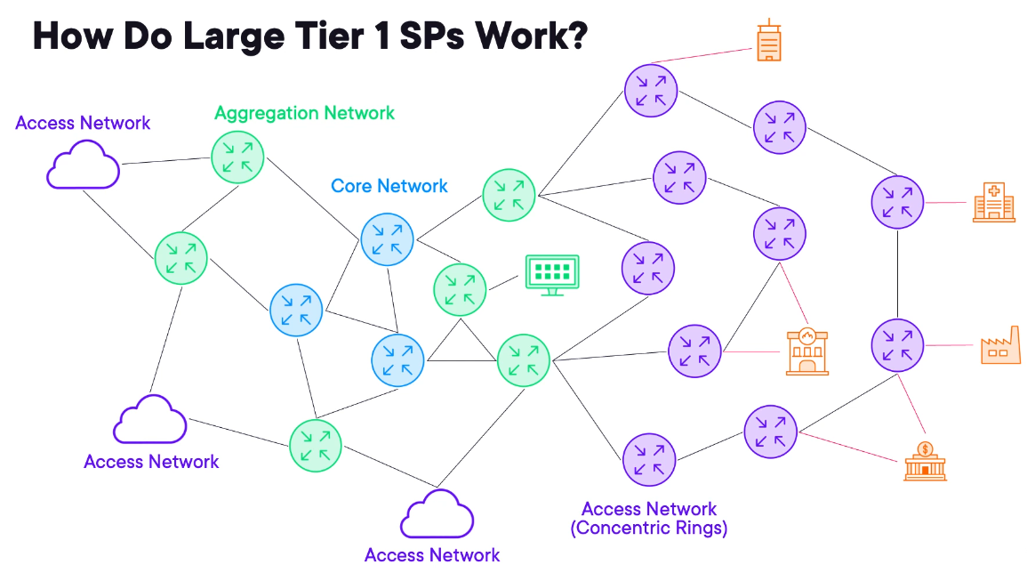
Architecture (15%)
Modern Service Provider Architectures
Basic SP Hierarchy: Core, Aggregation, and Edge
Tier1 or National Service Provider.
Core Network
- it is at the centre of the network, these are high throughput low feature devices.
- Customers never connect to the core.
Aggregation Network
- Adds resiliency and are built for speed.
- The primary objective is to consolidate connectivity from various access networks.
Access Network
- Where customer connects
- Usually Concentric Rings
Reusing Cable TV Lines for Internet via DOCSIS
DOCSIS
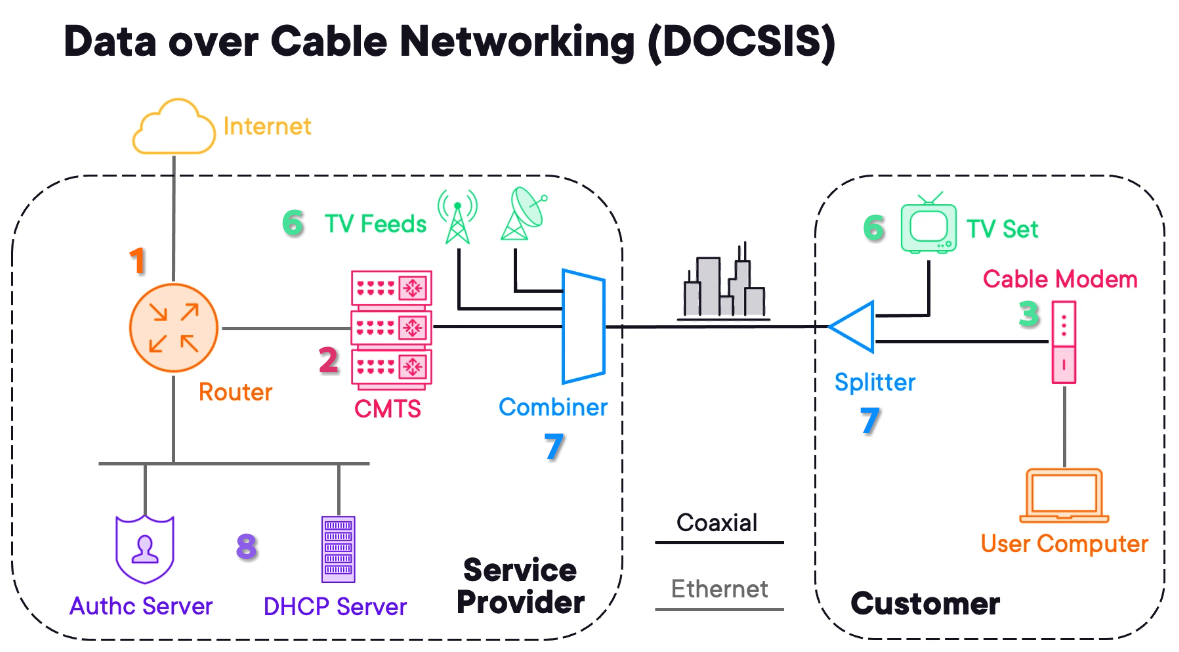
The formal name is Data Over Cable Service Interface Specifications.
1) The Service Provider has an aggregation router or router and the customer a computer.
2) The carrier router connects to a cable modem termination system (CMTS). This device aggregates connections from cable subscriber.
3) To connect to the CMTS the customer needs a Cable Modem.
4) The version of DOCSIS needs to match between the CB & CMTS.
5) The Coaxial network was used to provide data services.
6) The carrier has multiple services to deliver. Like TV Feeds from satellite and broadcast.
7) A combiner is added on the carrier side and a splitter on the customer site to split the different signals.
8) To avoid unauthorized use, the provider adds Auth. Servers and DHCP Servers to hand IP to the client.
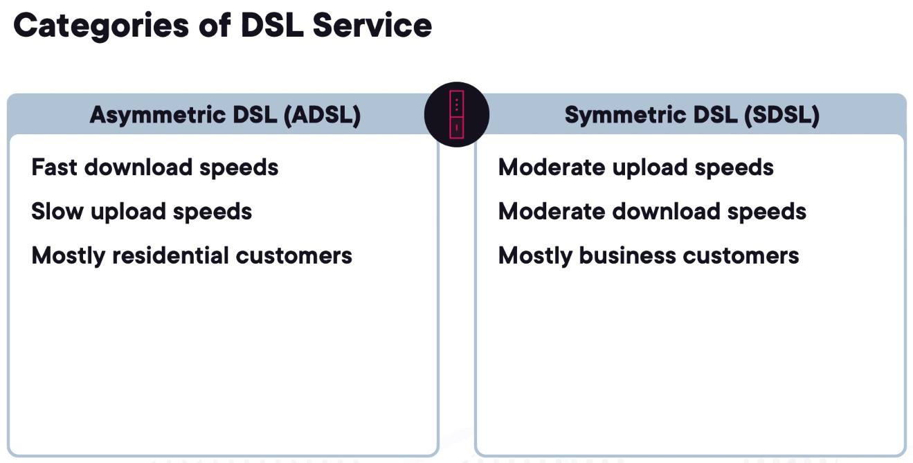
Reusing Telephone Lines for Internet via DSL
ADSL/DSL
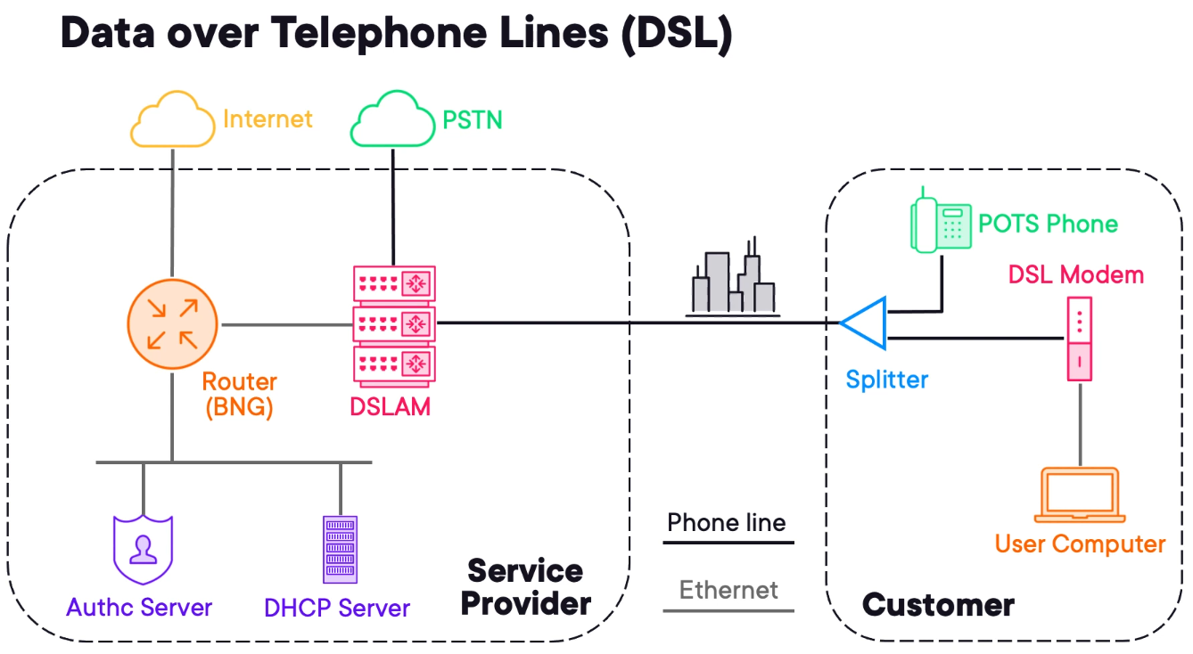
Digital Subscriber Line or DSL leverages the existing telephone connection.
1) The provider needs a DSLAM (Digital Subscriber Line Access Multiplexer) it aggregates connections from subscriber modems.
2) The customer uses a splitter to split the PSTN (phone) signal from data.
3) It is common to ADSL services to use pppoe as authentication methods and DHCP to handle IP Addresses.
What Is a GPON and Why Do I Care?
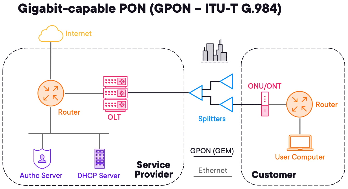
Many urban and suburban areas migrated to dedicated data networks often using fibre optics cables.
1) An Optical Line Terminal (OLT) is used to aggregate GPON connections from customer sites.
2) The end customer has an Optical Network Unit (ONU) or Optical Network Terminal (ONT). It is common for customers to connect a router to the service.
3) PON is called passive because the splitters do not require power to operate.
4) Like DSL & DOCSIS authentication servers and DHCP will be used to manage the customers.
GPON is not ethernet based. GEM stands for GPON Encapsulating Method.
Common Fiber Termination and PON Types
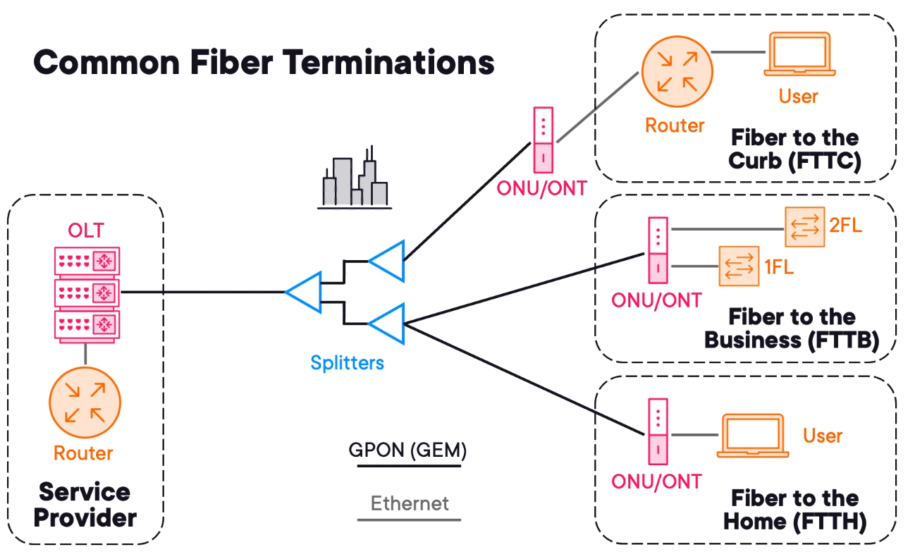
FTTH
Fibre to the Home is delivered with ONU/ONT, normally a router.
FTTB
Fibre to the Business the ONU/ONT is installed into a rack with further infrastructure behind it to support the users.
FTTC
Fibre to the Curb is when the bare fibre (or the last mile uses copper) is presented on the customer premises. Allowing the ONU/ONT to be located in another location minimising costs.
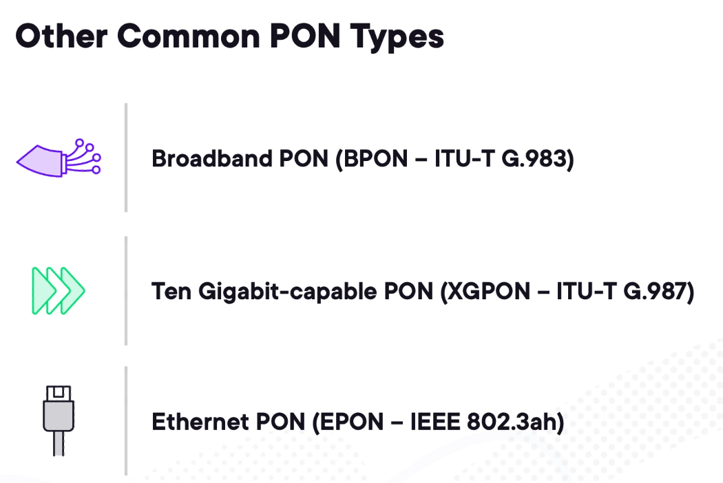
BPON
BPON is the predecessor of GPON which is much slower. Most ISPs are migrating to GPON.
XGPON
XGPON is a 10G capable solution. The operation is the same only that it is 10G capable.
EPON
Ethernet PON recycles Ethernet.
5G Cellular Networks and Device Mobility
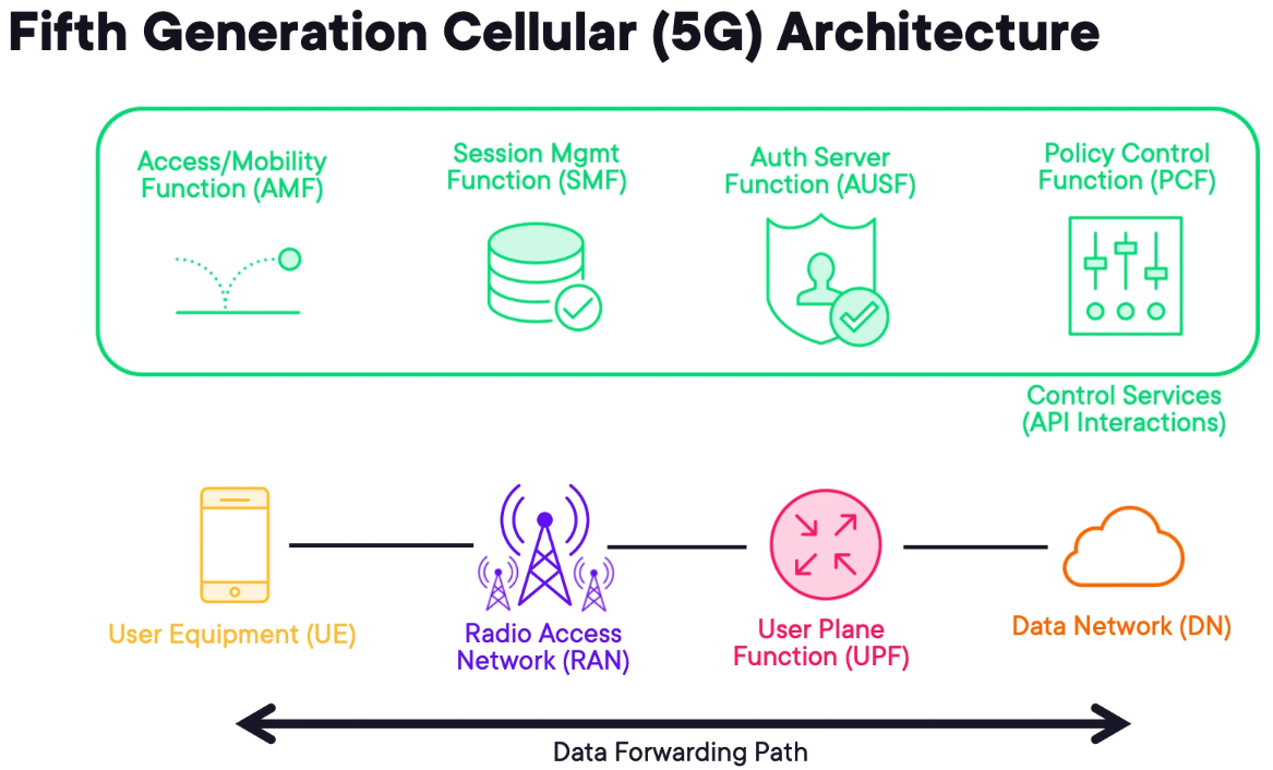
User Equipment (UE) - is the customer equipment. It can be a phone or cellular-enabled router.
Radio Access Network (RAN) - the UE connects to a cell tower which is part of the radio access network or RAN. Cell towers will be connected to the access network.
User Plane Function (UPF) - to access resources, the user accesses a UPF, essentially a router connected to an upstream Data Network (DN) that typically leads to the internet.
- In a private deployment, the DN can also represent a business network.
Session MGMT Function (SMF) - is responsible for maintaining sessions with the User Equipment.
Access/Mobility Function (AMF) - is used to onboard, track and migrate users while they roam.
Auth Server Function (AUSF) - ensure that only authorised users use the network
Policy Control Function (PCF) - apply traffic prioritisation to improve client experience.
Other control protocols are being omitted for brevity that can communicate laterally using APIs. For example, the AUSF can inform the SMF of an authentication failure and the SMF can purge the record from its database.
By decoupling these services it is possible to create a standard vendor-neutral environment that can scale.
To provide seamless roaming in cellular networks, 5G relies on tunnelling between the RAN and the UPF.
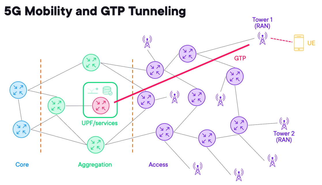
A protocol called Generic Packet Radio Service Tunneling Protocol (GTP) is used to connect the RAN to the UPF.
GTP allows wireless traffic to be transported to a central location when egressing from the cellular network.
When the UE roams it must maintain its IP address, once the UE is migrated to tower 2 it will transfer traffic back to the UPF using GTP.
UPF to DN connections often exist in the aggregation layer to service a geographic region.
IPv6 Transition with NAT44 and NAT64
NAT is one of the most commonly deployed technologies in networking.
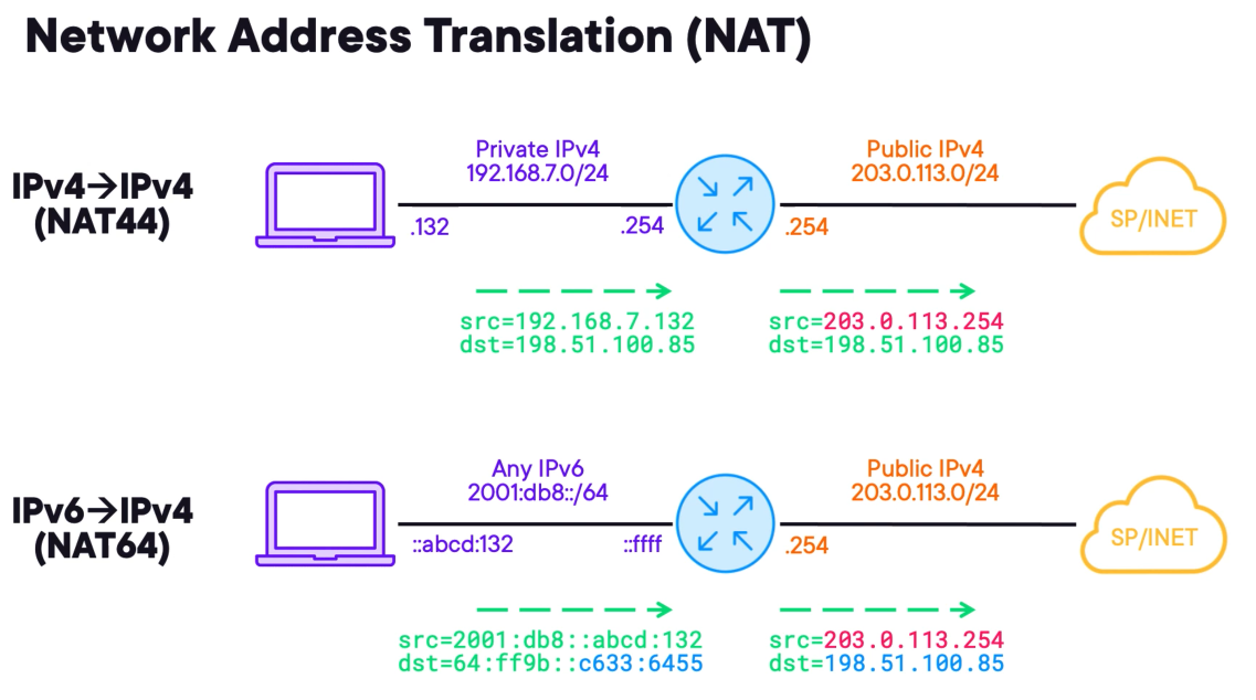
NAT44 - is used to translate IPv4 addresses. In the example, the private IPv4 is being translated into the public IP address.
NAT64 - is used to translate IPv6 into IPv4 addresses. It is most complex because it requires translating the source and destination addresses at the same time.
The post-NAT64 source IPv4 addresses must come from a dynamic public pool or a single public IPv4 address.
This allows IPv6 clients to access IPv4 resources. The IPv6 clients must target specific addresses that are IPv6 representations of IPv4 destinations.
The IPv6 address space of 64:ff9b::/96 fills the first 96 bits of the IPV6 destination with low-order 32 bits coming directly from the IPv4 destination.
A technology known as DNS64 works in concert with NAT64 to respond to client quad 8 queries with WKP-based destinations enabling seamless communications between IPv6 and IPv4.
Tunneling IPv6 over IPv4 with 6rd
An alternative to translating between IPv6 to IPv4 is to tunnel IPv6 over IPv4.
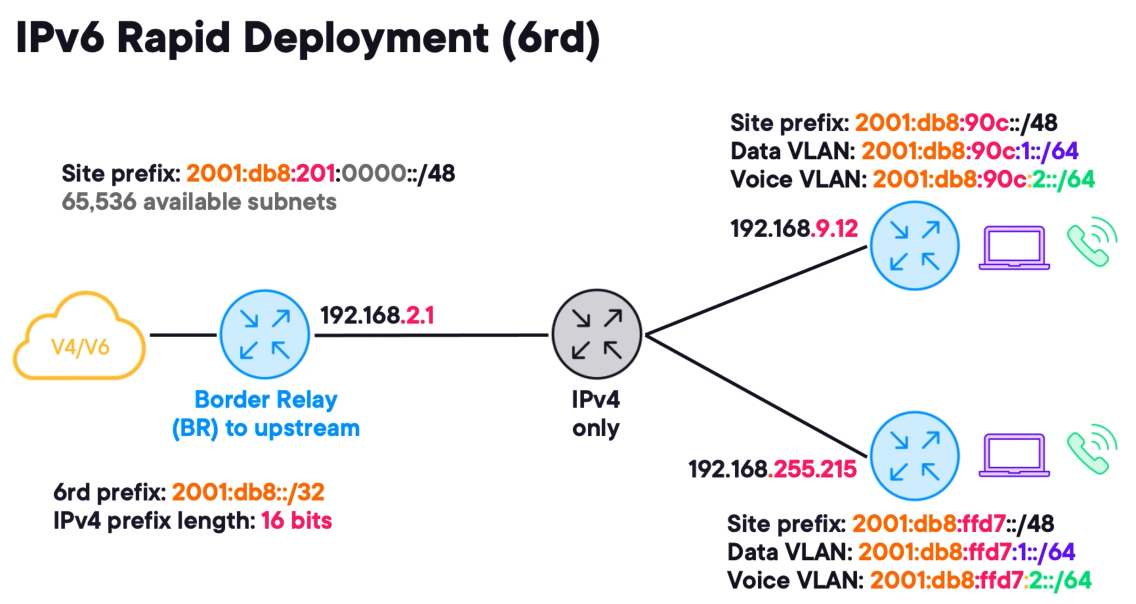
IPv6 Rapid Deployment (6rd) - the entire 6rd network is summarised within a general 6rd prefix.
The prefix is further divided between individual sites. And using subnetting administrators can determine how many networks are needed in each site.
This is achieved by masking redundant bits in the IPv4 underlying addresses.
The example in the picture uses a 6rd prefix of 2001:db8::/32 . Let's assume that all CPEs have the same first two octets this means that only the lower 16 bits are relevant.
Encoding redundant bits in the 6rd tunnelling address is unnecessary because it will waste address space.
To uniquely identify a prefix for a site, begin with the general 6rd prefix of 2001:db8::/32 and append the lower order 16-bits for each site underlay IPv4 address
This results in a unique IPv6 /48 prefix for each site and assuming we will only create IPv6 /64 networks this provides 65,536 available subnets.
6rd is totally stateless and has no signalled controlled plane it literally has a limited scale in this regard.
To exit a 6rd network at least one upstream router is identified as a border relay or BR, the remote sites rely on a static default IPv6 route towards this border relay to access the IPv6 internet.
Tunneling IPv4 over IPv6 with MAP
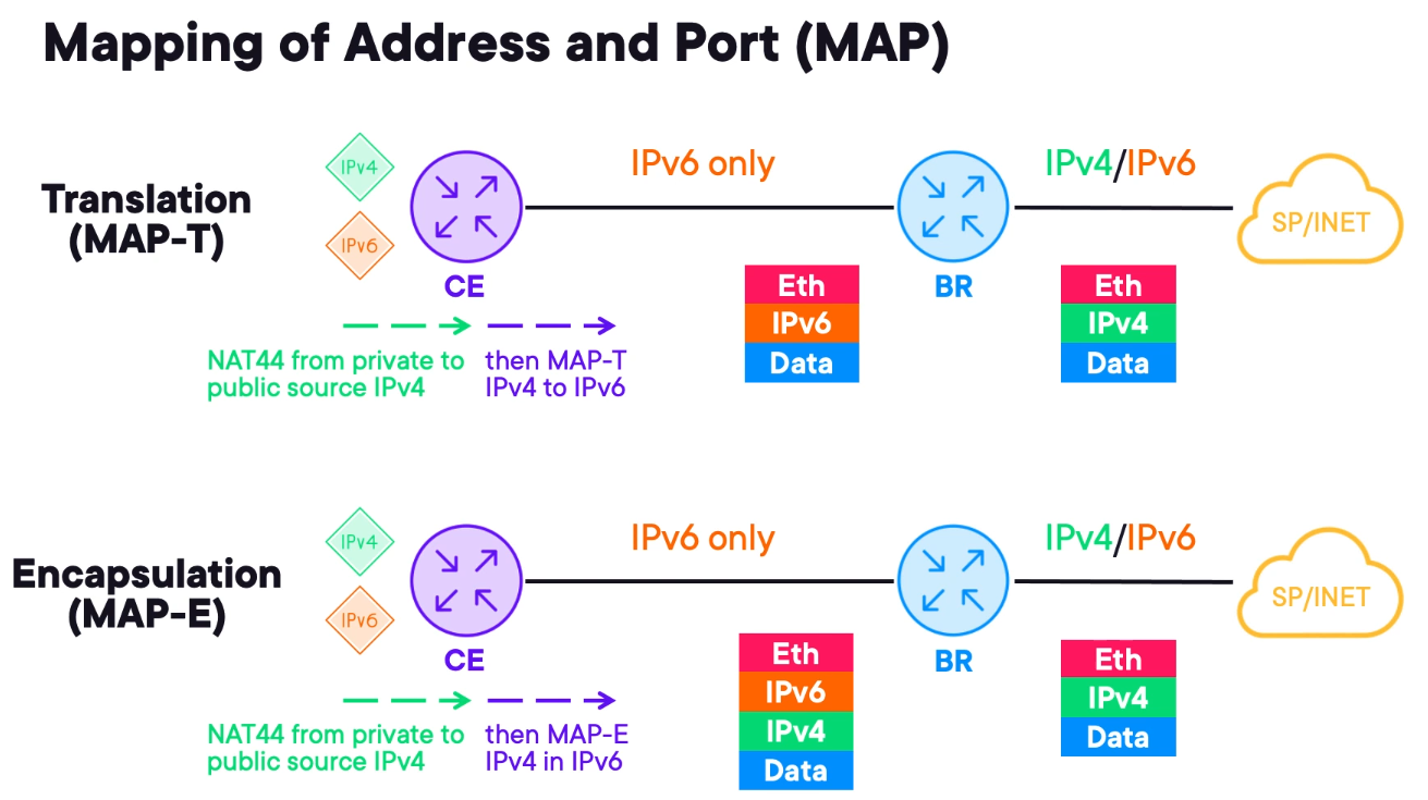
It utilises layer 4 port information in constructing IP headers. The general MAP technology involves a CE device with IPv4 behind it and IPv6 if the device is dual-stacked.
The transport network for the BR is IPv6 only. This way it is designed to provide IPv4 connectivity over an IPv6 network.
The CE device performs two important functions:
1) It performs traditional NAT44 translating the private source into a public source. This address is not directly configured on the CE but inferred using EA bits. This process is similar to 6rd and it is possible to specify a degree of uniqueness for port information.
Translation (MAP-T) - translates between IPv6 and IPv4 using layer 4 port information, with a NAT44 completed, the router then translates the IPV4 packet into IPv6.
The resulting IPv6 packet is forwarded to the MAP-BR and upon receiving it translates back into 1Pv4 finally, the IPv4 packet is forwarded to the internet towards the original destination.
Encapsulation (MAP-E) - It relies on IPv6 tunnelling instead of translation. After performing NAT 44 the device encapsulates the IPv4 packet in the IPv6 and forwards it to the MAP-BR. The difference is that the IPv4 packet remains unchanged inside the IPv6 packet.
It avoids the double translation of MAP-T but as encapsulation slightly reduces the customer payload size.
Tunneling IPv4 over IPv6 with DS-lite
DS-lite is also known as Dual-Stack Lite. This technology allows access to IPv4 resources over an IPv6 transport network.
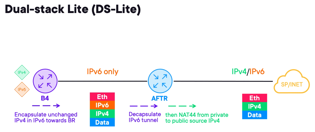
B4 - represents the customer edge device. It tunnels IPv4 inside IPv6 similar to MAP-E towards the AFTR.
The IPv6 tunnels are casually called soft wires.
Address Family Transition Router (AFTR) - upon receiving an encapsulated IPv4 packet the AFTR decapsulates it and performs NAT44.
The major advantage of DS-Lite is that the CE does not need to do NAT. It only tunnels traffic over the existing IPv6 network to the large NAT44 router. This minimises changes to the customer hardware and configuration.
However, it may require a software patch to add IPv6 tunnelling support to the CPE.
The drawback is NAT44 happening on the edge core devices. It can become expensive and does not scale. Unlike MAP, which distributes the complexity of NAT44 across many CEs.
Product Software Architectures and Availability Features
Understanding Cisco IOS and IOS-XE Architecture
Cisco IOS
Cisco IOS was developed in 1980 and is a monolithic, upgradable through a single binary file.
However, all processes share the same address space and if one service had a memory leak the whole system would be impacted.
IOS-XE
Addresses the Cisco IOS issues packaging the operating system into a daemon (IOSd).
It does not address bugs in features but since it is decoupled from the drivers it allows the administrator to treat the platform and the OS as two different things.
- It is possible to insert, reboot and upgrade hardware modules without rebooting the entire operating system.
- There are also new CLI commands specific to the underlying platform, providing additional visibility to network administrators.
- Some platforms allow the hosting of additional applications such as traffic generators, and monitoring scripts.
Cisco almost fully replaced most of its IOS products with IOS-XE.
What Makes Cisco IOS-XR Different?
IOS-XR provides granular software modularity. It creates separate memory spaces for different services.
This prevents a service that has a memory leak from crashing the device and can be troubleshooted separately.
The OS uses a micro Linux distro based on Winriver Linux. The older version uses QNX neutrino instead.
There is no monolithic system controlling the device. All features are installed as packages. These packages can be downloaded from Cisco like BGP, OSPF, MPLS.
The packages can be installed while the device is running without needing to reboot the device.
IOS-XR can also host apps like IOS-XE.
The system modularity adds more complexity since there are more things to manage.
High Availability with Non-stop Forwarding (NSF)
Some Cisco devices have redundancy built into a single device.
A device with redundancy has multiple routing processes (RP) which is the brain of the router and host control plane functionality such as routing protocols.
The line cards (LC) are responsible for data forwarding and are controlled by the RPs.
If the control plane fails the device becomes useless. To mitigate this issue 3 technologies were introduced.
- Non-stop Forwarding (NSF);
- Stateful Switch Over (SSO);
- Graceful Restart (GR)
GR is protocol-dependent, and Cisco implemented it in OSPF, IS-IS, BGP, EIGRP and LDP.
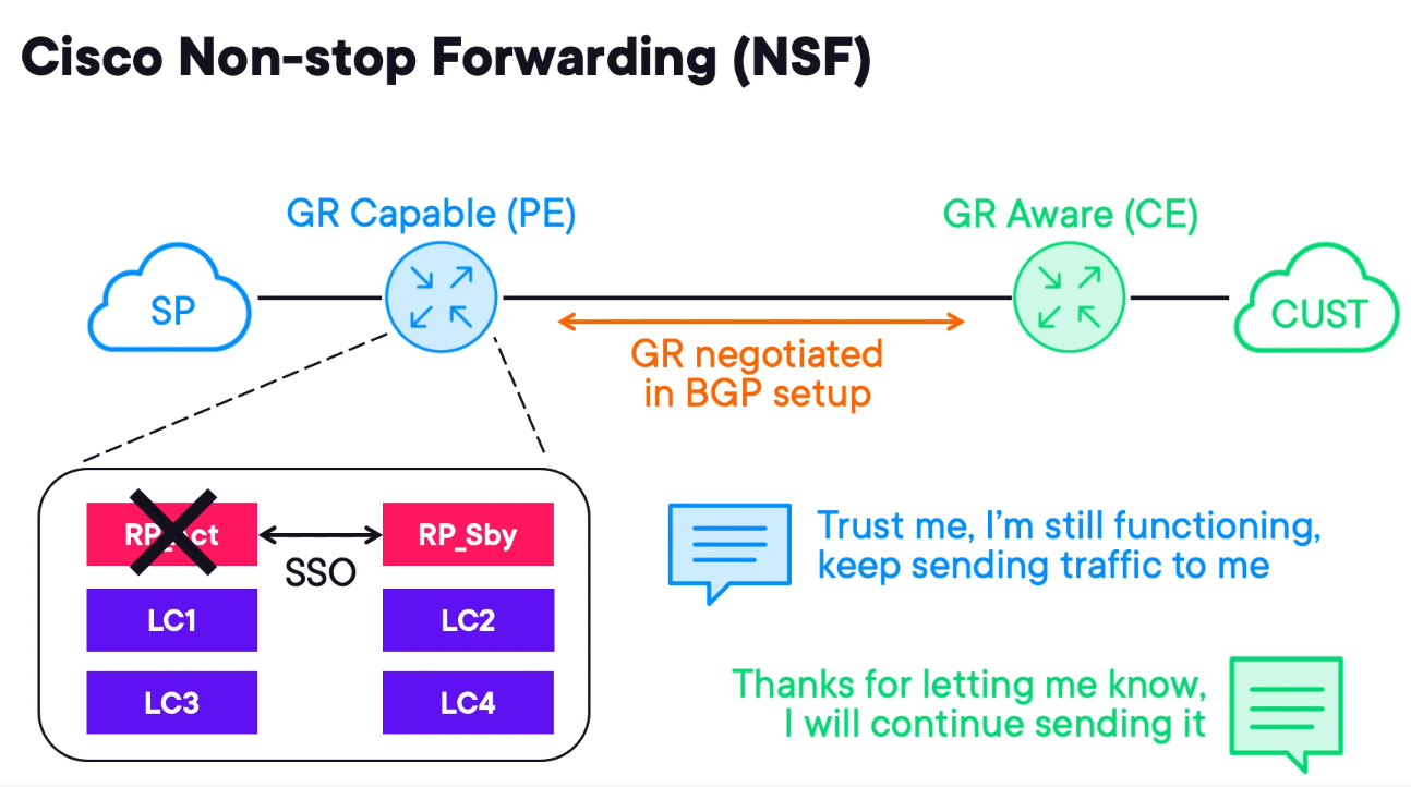
A device can be GR capable or GR aware and participate with a neighbour that is GR capable.
Consider a PE (GR capable) and a CE (GR aware). If the PE suffers an RP failure it can announce it to the CE and the CE will continue to forward traffic through the PE despite the control plane failure because NSF is enabled.
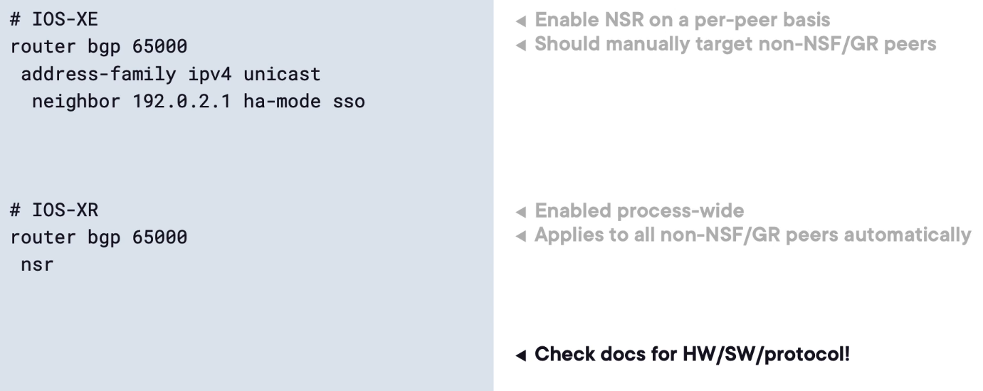
Non-stop Routing (NSR) as a Local Alternative
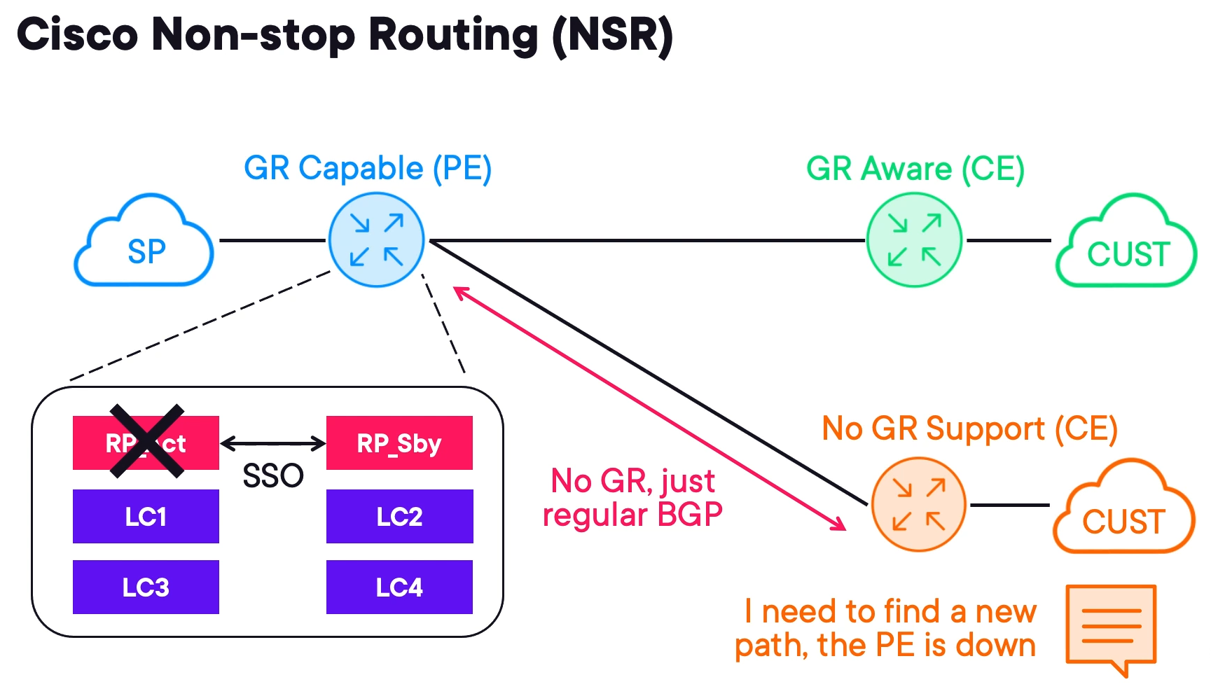
A service provider has a PE with multiple RPs and some of the CEs attached are not GR-aware. This is when Non-stop Routing (NSR) comes into play.
When the RP fails it signals to GR aware devices about the failover. However, non GR aware devices may converge during a failover.
Cisco devices prefer NSF when available and it is enabled by default.
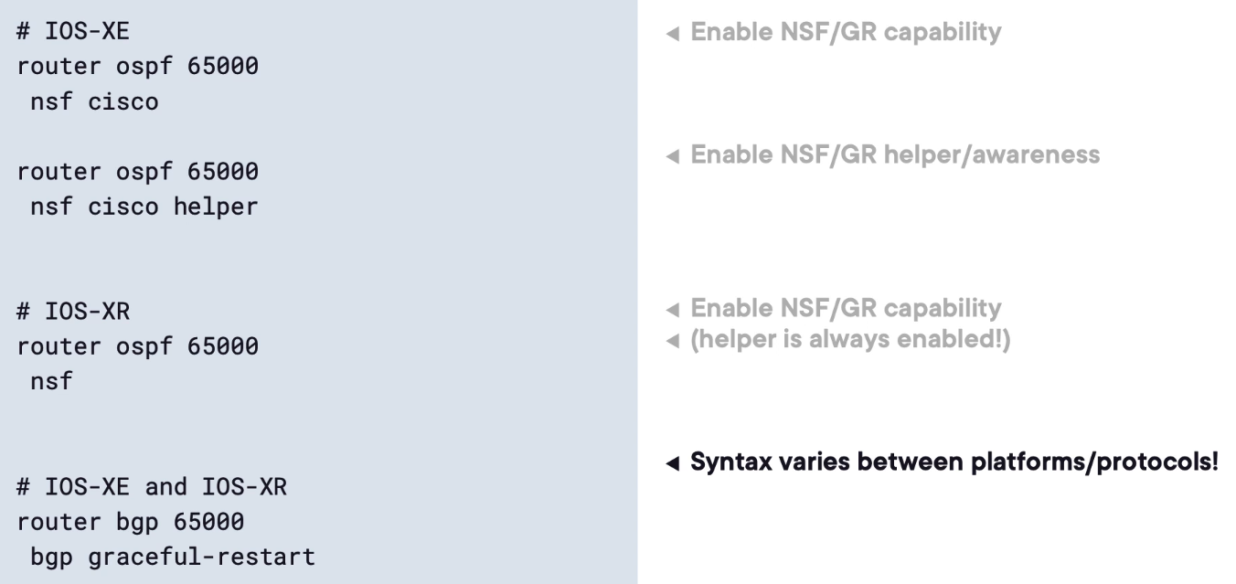
NSF and NSR Configuration Examples
Service Provider Virtualization Techniques
Improving Service Flexibility with Virtualization
Imagine a service provider point of presence (POP) in a Data Centre with a collection of servers that can run virtual machines.
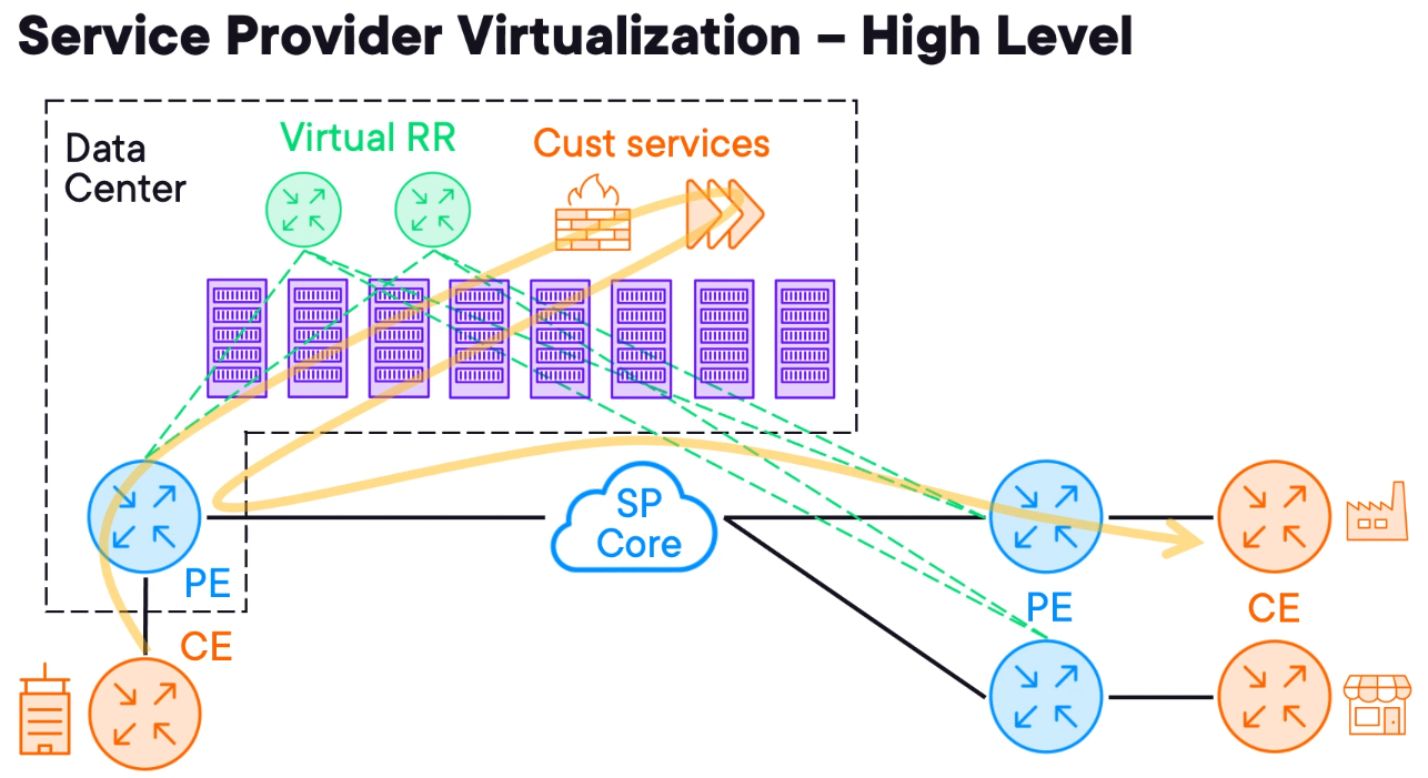
The servers are connected to the PE making them accessible anywhere within the carrier network.
This design helps the service provider to reduce costs when deploying network nodes. For example, the SP can use virtual routers as BGP route reflectors because the route reflector is limited to the control plane any virtual machine can run it as a virtual router.
A more complex approach is to use virtualisation to directly serve customers, and thanks to these hosted POP data centres, the SP can provide more than transit services.
Virtualisation solutions like VMware or HyperV can be used however, most SP uses OpenStack.
Want Your Own Cloud? Consider OpenStack
The easiest way to think about OpenStack is as a public cloud provider, except that it uses open-source software and is hosted on-premises.
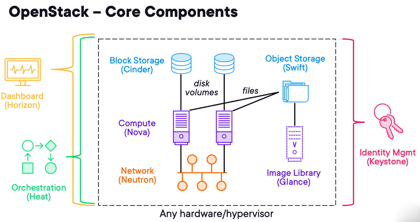
OpenStack is based on a modular architecture. There are six primary OpenStack components that handle compute, network and storage functions for on-demand VM provisioning. A bunch of other components enable additional features, such as dashboarding, bare metal provisioning, containers, secrets management and telemetry. In order to handle this complexity, organisations often use OpenStack Charms for fully automated OpenStack installation and post-deployment operations.
Nova
Nova is the primary compute engine of OpenStack, responsible for instance scheduling, creation and termination. In order to ensure widespread interoperability, Nova supports a wide range of hypervisors, including QEMU/KVM (the most commonly used today), Hyper-V, VMware ESXi and Xen.
Administrators can deploy virtual services that customers demand. This may include NetFlow collectors, virtual firewalls, WAN accelerators or other services that customers introduce into the transport network.
Glance
Glance is an image service, responsible for uploading, managing and retrieving cloud images for instances running on OpenStack. Glance works across a variety of stores to provide the most convenient location of images for organisations.
Neutron
Neutron provides network connectivity between OpenStack instances, enabling multi-VM deployments. For this purpose, Neutron uses various software-defined networking (SDN) technologies, including Open Virtual Network (OVN), Open vSwitch (OVS), Juniper Contrail, Cisco ACI, etc.
Cinder
Cinder is a storage component that is responsible for provisioning, management and termination of persistent block devices. Those can be later attached to the instances running on OpenStack to enable persistent block storage.
Swift
Swift is another storage component that provides a highly available and scalable object storage service similar to Amazon S3. It enables storing and retrieving unstructured data objects using a RESTful API for both OpenStack services and instances running on the cloud.
Keystone
Keystone serves as an identity service, providing authentication and authorization functions for the users in order to enable multi-tenancy. Keystone can be easily integrated with external identity systems, such as lightweight directory access protocol (LDAP) or Active Directory.
Horizon
It is the dashboard service and provides a graphical interface to manage all the resources in an OpenStack deployment. Horizon is layered on top of APIs and allows service providers to create self-service portals hiding the Horizon interface from customers.
Heat
The orchestration service is known as heat and can be used to deploy entire cloud applications via templated using a variety of APIs deployed in a proper sequence. Heat can use or deploy images stored in Glance and interconnect them using Neutron.
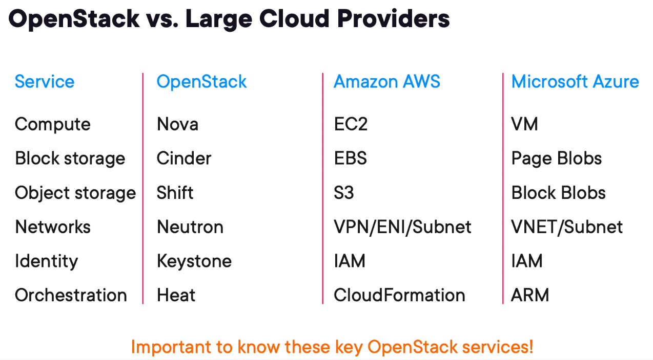
Comparing OpenStack to Amazon AWS and Microsoft Azure
Network Functions Virtualization (NFV) Architecture
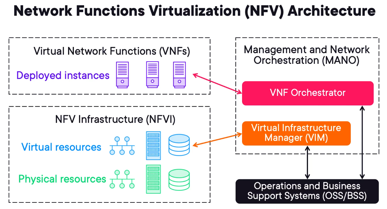
Network Functions Virtualization is the logical architecture describing how Virtual Machines are linked (NFV).
There are 3 main components of an NFV solution.
NFV Infrastructure (NFVI) - encompasses the virtual and physical resources allocated for computing, storage and networking.
Virtual Network Functions (VNFs) - these are the virtual machines in a VMWare context.
Management and Network Orchestration (MANO) - is composed of VNF Orchestrator and Virtual Infrastructure Manager (VIM) that are responsible for controlling the NFVI and VNFs respectively.
Operations and Business Support Systems (OSS/BSS) - will interface with VIM and VNF to create customer-specific services.
Virtual Network Function (VNF) Example Designs
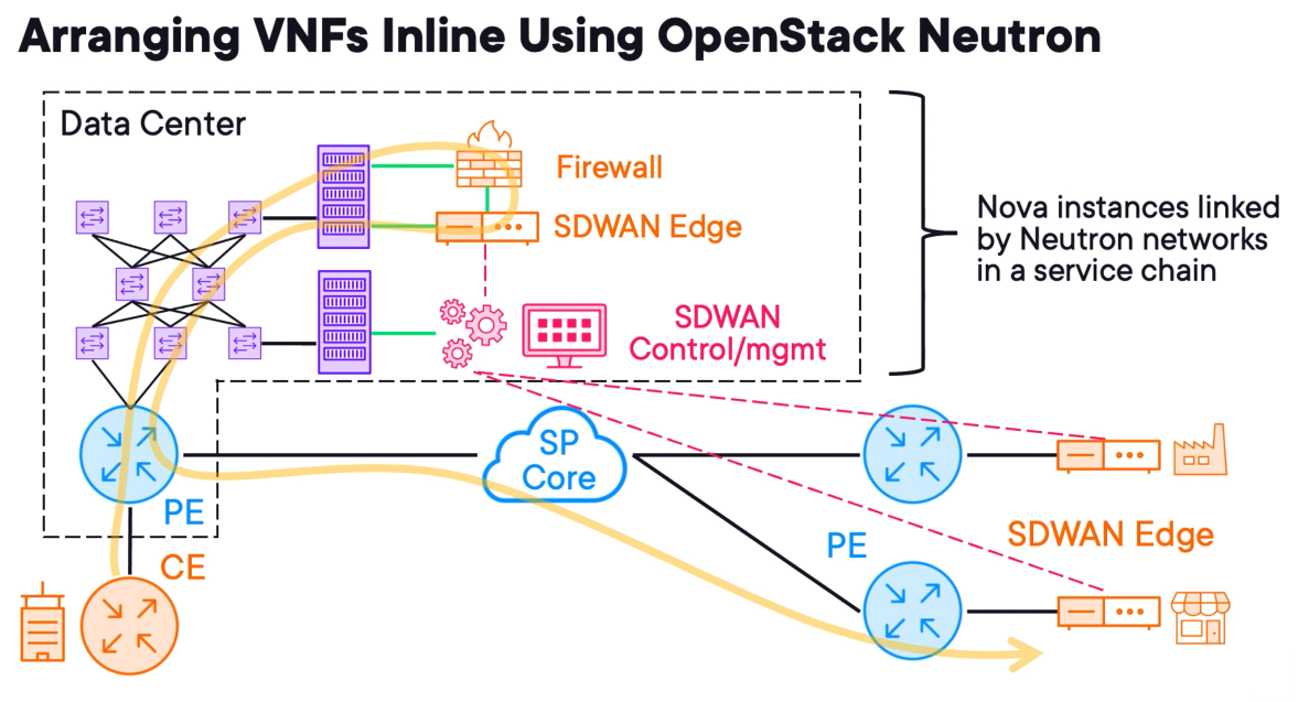
The customer requires a firewall and additionally, they want to deploy an SDWAN solution in the future.
Firewall
To deploy the firewall the Service Provider operator will log into Horizon and deploy a new instance using Nova.
The firewall image would be stored in Glance and its block storage in Cinder.
The Neutron service would connect the customer access circuit to the firewall inside the interface shown in green.
If the provision is automated the SP would use Heat to orchestrate the pipeline for such service deployment.
SDWAN
Let's assume that there are only three components, an edge router, a central control plane node, and a central management plane node.
The edge router comes after the firewall, so OpenStack Neutron connects the outside of the firewall to the inside of the SD‑WAN edge router. The outside of the SD‑WAN edge router is connected into the service provider network.
The SD‑WAN control plane and management plane nodes are like BGP route reflectors in that they are not used for transit.
These are just virtual instances requiring network access into the customer tenant network so that SD‑WAN edges can connect to them.
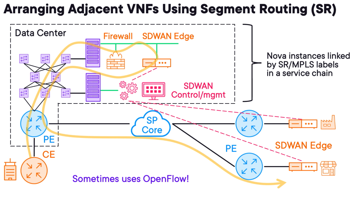
Let's briefly revisit the previous example using MPLS segment routing instead of using OpenStack Neutron to connect our devices.
This architecture is more abstract because the firewall, SD-WAN edge router and SD-WAN controller are all placed alongside one another and the deployment sequence doesn't matter.
The forwarding path is still the same as before, except the services are looped in rather than arranged in a line using virtual networks. Customers will never have insight into this flow, but carriers may find this easier to manage, even though it is more technically challenging to implement.
Some organisations use OpenFlow to fully centralize control plane operations and enable per-flow forwarding.
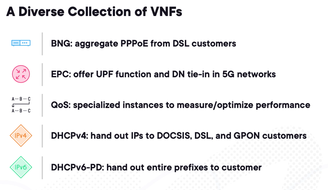
Additional VNF Types and Their Purposes
MPLS and Segment Routing (20%)
Implementing Cisco Multiprotocol Label Switching (MPLS)
Case Study
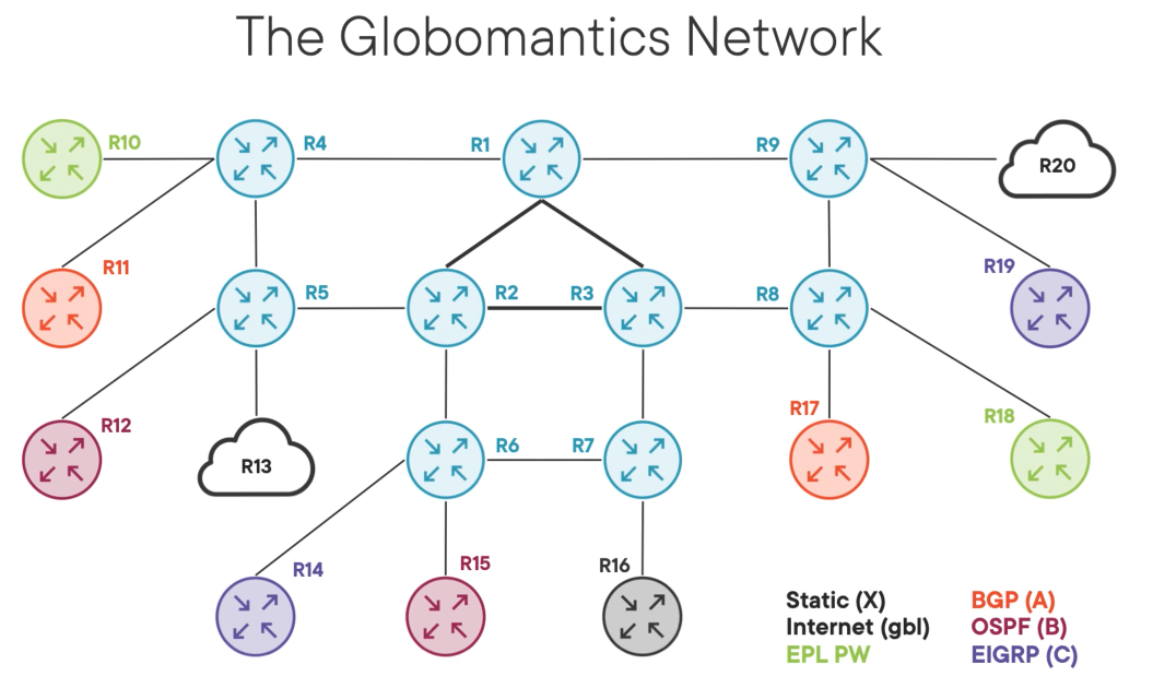
The blue routers are the core network and MPLS-enabled designed for fast transport.
R1, R2 & R3 are the inner core and OSPF prefers them.
R13 - is a small ISP
R20 - represents the internet and it is a large ISP.
Globomantics sits in between them providing internet transit service in the global routing table.
Each customer is represented by a different colour and our job is to isolate the customers.
R16 - is a carrier-managed extranet and some customers need to access services behind it.
The customer in green needs L2 services to connect R10 & R18.
Reviewing the MPLS and LDP Fundamentals
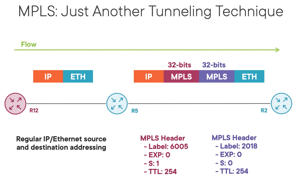
MPLS information is inserted between the IP and ETHERNET header.
MPLS is dynamic and low effort since we don't have to include forwarding information in the headers.
It is common for multiple headers to exist in series creating a header stack. Each header is known as a sheen header and is 32 bits in size containing 4 components.
Label: is 20 bits and is like a destination MAC.
EXP: is used to signal quality of service in MPLS networks and is 3 bits in size.
S: signals the bottom of the MPLS header stack.
TTL: is 4 bits in size and it is used to prevent loop.
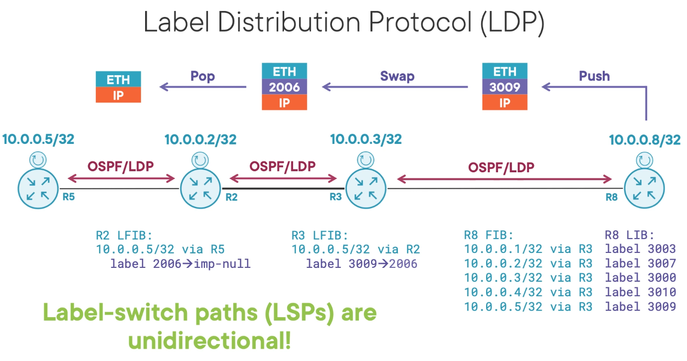
In most designs, LDP runs in conjunction with the IGP such as OSPF as a complementary protocol.
The IGP distributes routes and LDP labels. Like IGPs LDP uses local-link multicast to discover its peers then forms a neighborship to exchange MPLS labels.
In the Globalmantics example, all core links are LDP enabled.
Consider R8 in the topology, ignoring the transit links, R8 has a loopback of 10.0.0.8/32 and learns the other router loopback via OSPF resulting in the FIB (Forwarding Information Table) seen.
For each route learned from IGP, MPLS will assign a label. Because all 9 core routers know of each other loopback MPLS will distribute a label to all of them.
R3 will send 9 label mappings to R1 via LDP saying you can use label 3003 to reach 10.0.0.1/32 and so on.
Labels are dynamic and we don't care about them unless we are troubleshooting a problem. The labels are stored in the Label Information Base (LIB) and pre-programmed into the FIB for fast-forwarding when needed.
The label is locally significant to the adverting router. When R3 tells R8 that it can reach 10.0.0.5/32 through label 3009, R8 have to add an MPLS label when it sends traffic towards R5 through R3. This action is known as imposition or a PUSH operation.
When R3 receives label 3009 it consults its Label Forwarding Information Base (LFIB) it is like an IP table but instead maps labels to destination prefixes. Then, label 3009 on egress is replaced with label 2006.
On the last hop, because R5 is the last MPLS label switch path. R2 instead of performing a label SWAP it performs a label POP revealing the regular IP packet. This eliminates the need of a lookup and POP operation in R5.
Demo 1 - MPLS Lab
The first MPLS LAB requires OSPF to be configured. The article below will describe the LAB configuration.
Networking (30%)
Implement OSPF (v2)
The lab for this section can be found on the link below.
Neighbour adjacency
Before exchanging any topology information or updating the route table, an OSPF router must form adjacencies with its neighbors. In OSPF, two routers are considered adjacent only when they have completed the full process described below and are exchanging topology information.
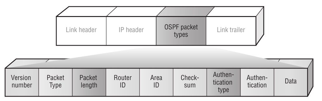
All OSPF messages share the same headers. The data field is different depending on the message type.
Router ID
A unique router ID (RID) is required by the SPF algorithm to uniquely identify each
router in the routing domain. The RID is a 32-bit value that is typically set to the system
address
Hello Message
The OSPF Hello packet consists of the following fields:
• Header—The OSPF header is the same for all five types of OSPF messages. In the Hello packet the type field has the value of “1.”
• Network mask —The network mask field contains the network mask for the interface that the packet is being sent on.
• Hello interval—The Hello interval is the interval at which Hello packets are sent on the interface. The Hello interval must match for all neighbors on the interface.
• Options—The options field contains several flags, including the E bit. The E bit is set to indicate that the router interface is not in a stub area. It is 0 (cleared) if the interface is in a stub area. This value must match for all neighbors on the interface.
• Router priority—The router priority field denotes the priority value used when electing the DR and BDR. A priority of 0 means that the router can never be a DR or BDR on the network connected to this interface.
• Router dead interval—If a neighbor does not send a Hello packet within the dead interval, the router assumes that the neighbor is not active and purges all information from that neighbor. This value must match for all neighbors on the interface.
• Designated router —This field denotes the elected DR.
• Backup designated router—This field denotes the elected BDR.
• Neighbor—This field varies depending on the number of neighbors the router has learned of on the interface. The RID of all neighbors seen on this interface is carried in this field. A router looks for its own RID in the Hello, to know that it is seen by its neighbors.
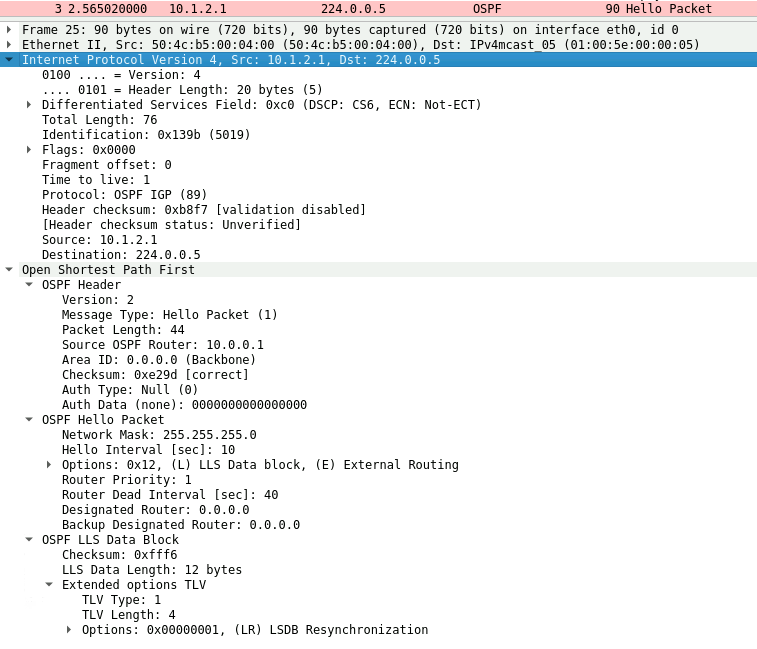
OSPF Neighbor Discovery
OSPF is a discovery protocol in that it will discover its neighbors. A neighbor is an OSPF router that is configured with an interface to a common network. The router sends OSPF Hello packets on the network and receives Hello packets in return. The Hello packets are sent to a multicast address (224.0.0.5).
When a router receives a Hello packet on an OSPF-enabled interface, the parameters are compared with the configuration of the interface. Certain values must match or the Hello is considered invalid and is ignored. The values that must match are as follows:
- Area ID
- AuType and authentication password
- Network mask
- Hello interval
- Stub flag (options field)
- Router dead interval
Once a router sees its own RID in the Hello received from a neighbor, it transitions to the 2-Way state and can elect a DR and BDR if it is on a broadcast network.
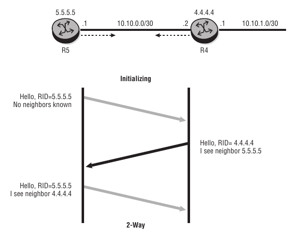
This process can be seen in the packet capture below.
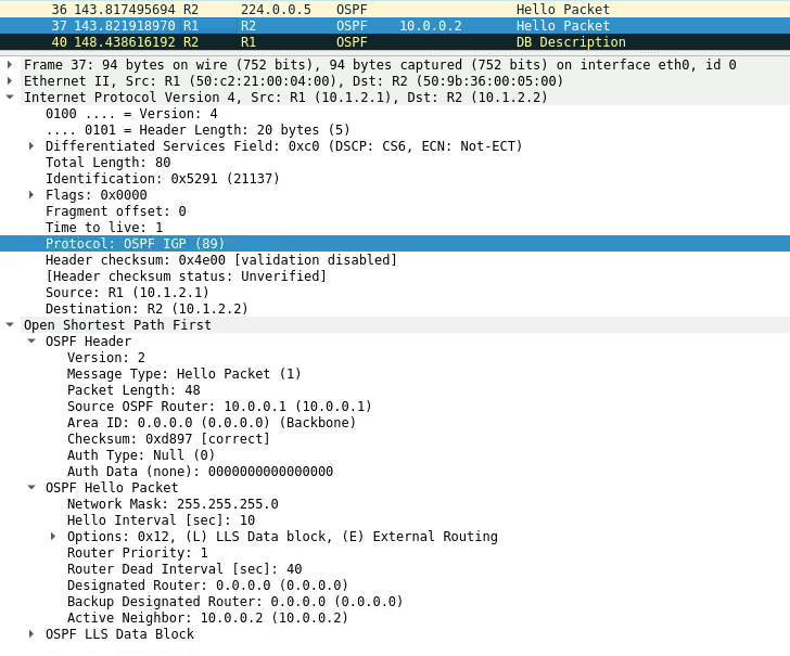
1) R2 sends a Hello Packet to the multicast address 224.0.0.5.
2) R1 receives the Hello Packet and transmits a Hello Packet to R2 saying it is seeing R2 as an active neighbor.
3) When R2 receives the Hello Packet OSFP enters in the 2-Way state.
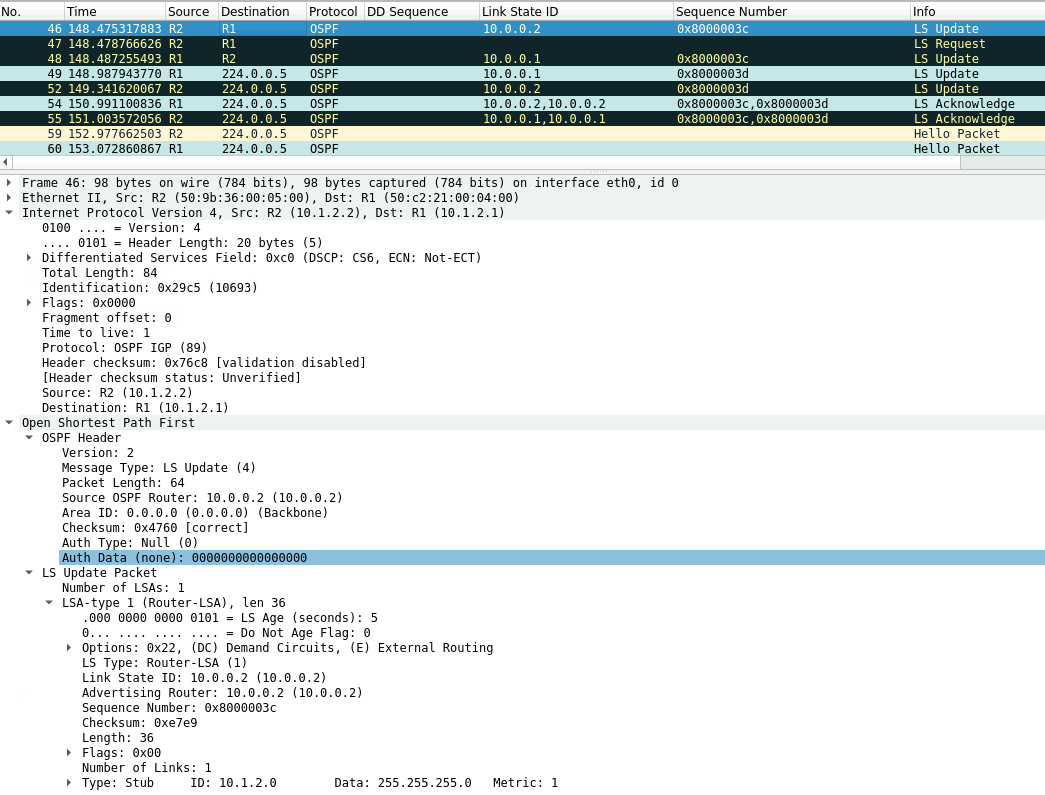
OSPF Exchange & DB Description Packet
This exchange happens between the routers described in this topology with the interface between R2 and R3 shutdown.
1) Both Routers sends DB Description(DBD) packets to determine the initial DBD sequence number for the exchange state.
2) R2 has a higher Router ID and becomes the master, thus its sequence number is used. In our example 9522.
3) R1 (Slave) sends its DB Description packet, describing its LSDB. Using the initial sequence number of 9522.
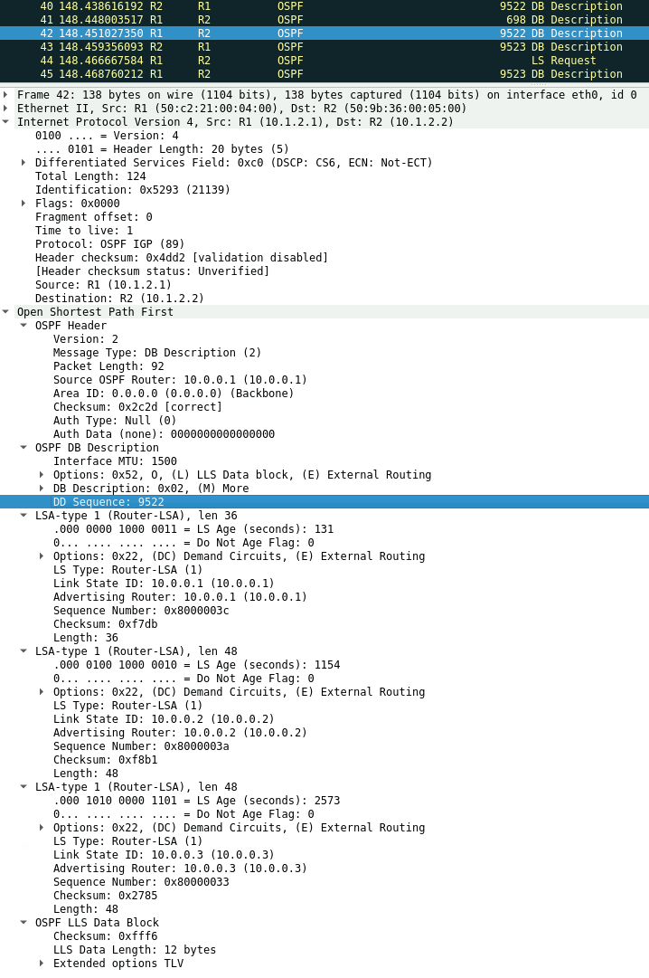
4) R2 (Master) increments the sequence number and sends a DBD packet describing its LSDB.
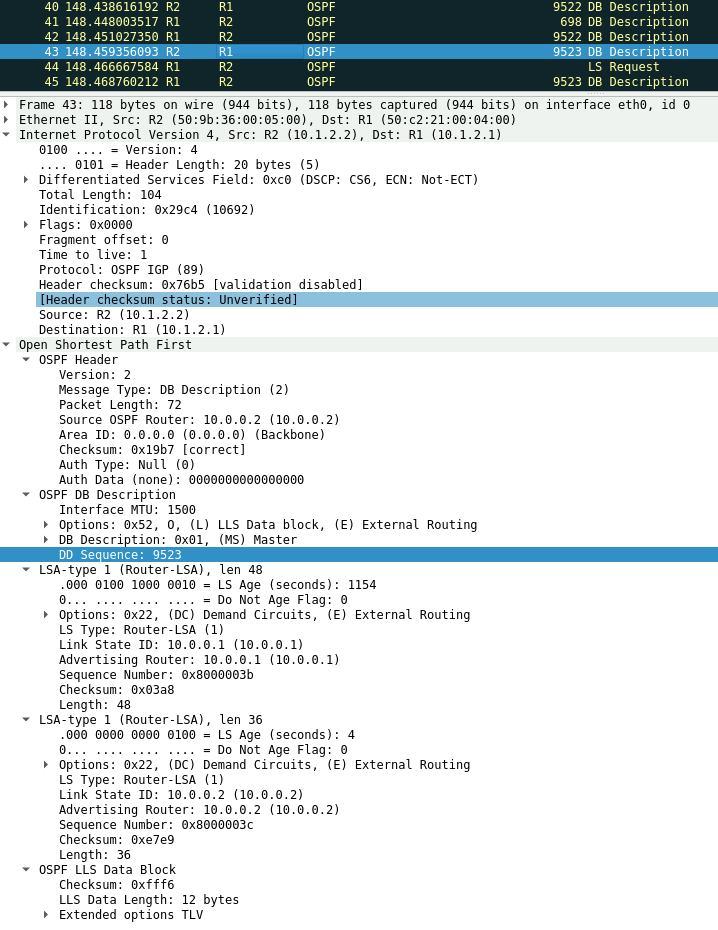
5) For each LSA in the DBD packet the router compares the LSA sequence number with its existing entry:
• If an LSA is unknown or if it is known but the advertised sequence number is higher, the receiving router requests the LSA in an LSR.
• If the network is already known and the sequence number is lower, the receiving router sends back an LSU with the up-to-date information.
• If the network is already in the database and the sequence numbers are identical, the receiving router discards the information.
In our example the sequence number of the LSA for 10.0.0.2 that R1 has in its Database is lower and an LS Request is sent to R2.
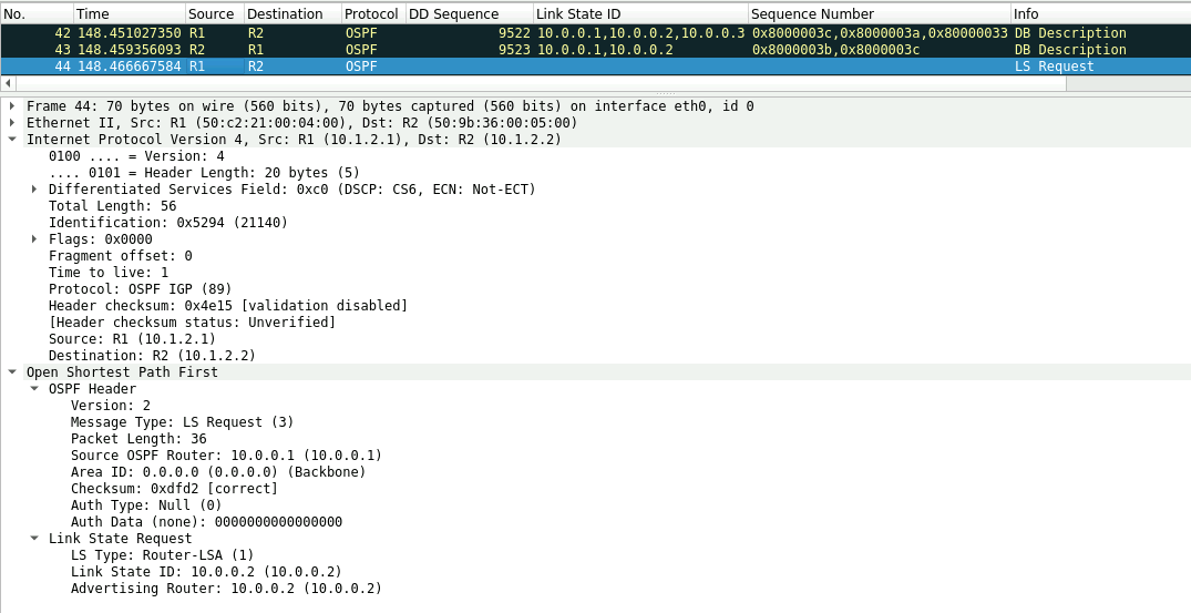
R2 also has a lower sequence number for the 10.0.0.1 LSA and and exchange of LSA update and LSR is exchanged between the routers as seen below.

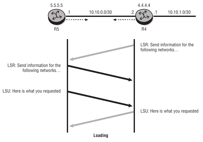
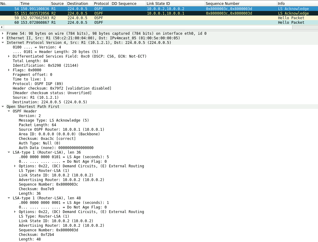
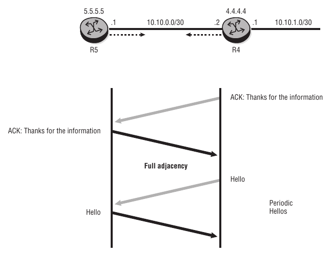
Link-State Acknowledgment Packet
In OSPF, LSUs are always acknowledged with link-state acknowledgments to inform the sender that the LSU has been received. After the exchange of LSRs and LSUs, both LSDBs are completely up to date, and the routers have formed a full adjacency.
1) R1 acknowledges the LSU received from R2.
2) R2 acknowledges the LSU received from R1, and the state changes from Loading to Full.
3) To maintain the adjacency, the routers send periodic Hellos to each other. The default interval is 10 seconds.
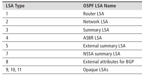
LSA Types
The reliable flooding of topology information throughout the routing domain is a critical aspect of OSPF’s operation. In OSPF, each router constructs a Router (or Type 1) LSA that describes the local topology as seen by the router. There may also be other types of LSAs generated to carry other topology details, as shown below.
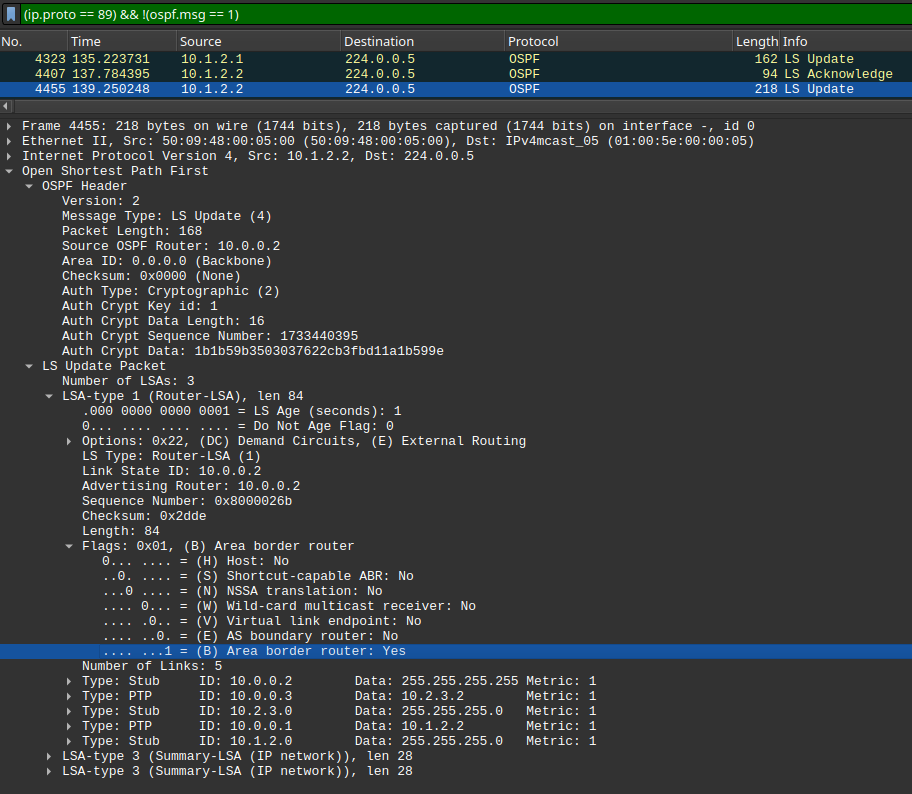
Router LSA Details (Type1)
Type 1 (Router) LSAs are generated by each OSPF router. Together with Type 2 (Network) LSAs, Router LSAs contain the basic topology information of the area.
Router LSAs are flooded to all the routers in the local area but are not forwarded between OSPF areas.
Remember that the Router LSA is transmitted to the neighboring routers in an LSU. The advertising router’s RID is used as the link-state Id for the Router LSA.
Here's the example of a type 1 LSA from and ABR router.
Network LSA Details (Type2)
Summary LSA Details (Type3)
Despite the name this LSA is not necessarily a network summary although it can be rather it simply includes prefixes from other areas also know as inter-area prefixes.
Type 3 summary LSAs are generated by an area border router, or ABR. An ABR is a router that is attached to two or more areas. When data traffic moves from one OSPF area to another inter area, it passes through an ABR.
So how does the ABR generate the type 3 LSA? We'll simply, it takes information from type 1 and type 2 LSAs, and it converts that information into a type 3 network summary LSA, and it sends it to the adjoining areas.
A Summary LSA is generated for every prefix listed in the LSDB for the area. Each Summary LSA describes only one destination, thus an ABR can generate many Summary LSAs if there are many prefixes in the LSDB. By design, the Summary LSA should be a true summary network advertisement rather than just a repetition of the individual prefixes from that area. This requires the configuration of manual summarization on the router by the network administrator.
LSA Aging
In OSPF, LSAs are considered valid until they reach the age of 3,600 (1 hour). At the age of 3,600, LSAs are removed from the database. When the age reaches ~1,800, the advertising router increments the sequence number and floods the LSA throughout the network. Although there has been no topology change, this refreshes the LSA in all the LSDBs.
OSPF Link Types
There are four different link types defined for OSPF. The Type field identifies which of the four types of links the entry describes. Depending on the type of link, the Link ID and Link data fields have different meanings.
• Type 1 (point-to-point link)—This entry is created for any point-to-point interface on which there is an adjacency with another OSPF router. (This includes an Ethernet interface that has been specifically configured as point-to-point.) The Link ID contains the RID of the neighbor, and the Link data field contains the IP interface address for the link. If the link is unnumbered (no IP address assigned), the Link data contains the interface index value. For each Type 1 entry, a Type 3 (stub network) entry is also created to describe the subnet.
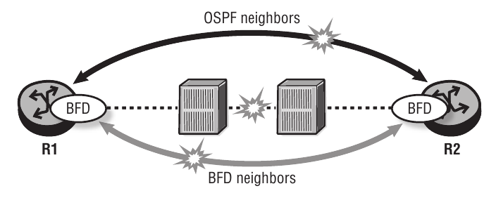
Bidirectional Forwarding Detection
BFD provides a lightweight network protocol that operates at the level of the physical interface to detect the loss of packet forwarding capabilities on the link.
It can be used between two OSPF neighbours to quickly detect link faults. Because the processing of BFD packets is handled by the IOM (Input/Output Module) and does not have an impact on the CPM, the transmission rate can be much higher and the failure detected much more quickly. When a BFD failure is detected on the interface, the routing protocol is signaled and responds immediately to the failure.
The BFD session is configured on the interface and enabled in the routing protocol. An interface with BFD enabled transmits UDP (User Datagram Protocol) packets at the transmit interval and expects to receive them at the receive interval. The transmit interval for BFD can be set as low as 10 milliseconds with a multiplier of 3, meaning that failures can be detected within 30 milliseconds.
Check our lab in this link which was configured to detect failures in 150 milliseconds.
OSPF Multi-Area Networks
OSPF (Open Shortest Path First) and IS-IS (Intermediate System to Intermediate System) both support hierarchy to improve their scalability. Hierarchy is implemented by allowing the autonomous system (AS) to be divided into multiple areas. However, routing between areas is handled differently, with only limited (or summary) routing information distributed between areas.
Reasons for Multi-Area Networks
In the early days of OSPF (early 1990s), routers had very limited processing and memory capacity compared to modern routers. Performing the SPF algorithm could be a very taxing process in a network of 20 to 30 routers.
The disadvantage of multiple areas is a greater complexity in design, configuration, and troubleshooting. Often the route to a destination outside the area takes the shortest path to the exit point of the area, which may not be the shortest path to the destination overall. Thus, hierarchy can lead to suboptimal routing between areas.
Modern routers have greatly increased processing capabilities and can handle link-state networks of several hundred routers. Thus, the need for multiple areas is much less than it used to be.
Backbone Network and ABRs
In an OSPF multi-area network, all areas are connected to the OSPF backbone area, which has Area ID 0.0.0.0. The backbone area must be contiguous, and all other areas must be connected to it. The backbone distributes routing information among areas. If it is not practical to connect an area directly to the backbone, it may be connected using a virtual link.
The other areas are connected to the backbone by area border routers (ABRs).
- Backbone router—A router that has at least one interface in Area 0 (backbone area). Backbone routers may be intra-area routers (only Area 0) or ABRs.
- Area border router (ABR)—A router that has interfaces configured in more than one area. Often, this is between the backbone area and one other area; however, it is possible that an ABR connects to multiple other areas.
ABRs set the "B" bit in their router LSAs as seen on the packet capture below.
OSPF Normal Areas
Normal areas contain LSA types 1,2,3,4 and 5. Refer to this link for all OSPF LSA types.
OSPF Stub Areas
A stub area must not contain Type 4 (ASBR) or Type 5 (External Summary) LSAs. The ABR does not flood these LSAs into the area. Instead, a Summary LSA (Type 3) for the default route is flooded into the area and is installed in the route-table of the intra-area routers in the stub.
The OSPF Multiarea Lab diagram, shows the router R7 is in a stub area. As seen on this output, the ABR floods a default route into the area.
OSPF Totally Stub Areas
A Totally Stub Area has only one exit point from the area, so Summary LSAs (Type 3) are not useful. The ABR is configured to filter Summary LSAs (Type 3) and the link-state database contains only Router (Type 1), Network (Type 2) LSAs from the area and a single Summary (Type 3) LSA with the default route from the ABR.